Drilling is one of the most complex machining processes. The chief characteristic that distinguishes it from other machining operations is the combined cutting and extrusion of metal at the chisel edge in the center of the drill. The high-thrust force caused by the feeding motion first extrudes metal under the chisel edge. Then it tends to shear under the action of a negative rake angle tool.
Nomenclature of a Twist Drill — The cutting action along the lips of the drill is not unlike that in other machining processes. Because of variable rake angle and inclination, however, there are differences in the cutting action at various radii on the cutting edges. This is complicated by the constraint of the whole chip on the chip flow at any single point along the lip. Still, the metal-removing action is true cutting, and the problems of variable geometry and constraint are present. Because it is such a small portion of the total drilling operation, though, it is not a distinguishing characteristic of the process.
The machine settings used in drilling reveal some important features of this hole-producing operation. Depth of cut, a fundamental dimension in other cutting processes, corresponds most closely to the drill radius. The un-deformed chip width is equivalent to the length of the drill lip, which depends on the point angle as well as the drill size. For a given set-up, the un-deformed chip width is constant in drilling. The feed dimension specified for drilling is the feed per revolution of the spindle. A more fundamental quantity is the feed per lip. For the common two-flute drill, it is half the feed per revolution. The un-deformed chip thickness differs from the feed per lip depending on the point angle.
The spindle speed is constant for any one operation, while the cutting speed varies all along the cutting edge. Cutting speed is normally computed for the outside diameter. At the center of the chisel edge the cutting speed is zero; at any point on the lip it is proportional to the radius of that point. This variation in cutting speed along the cutting edges is an important characteristic of drilling.
Once the drill engages the workpiece, the contact is continuous until the drill breaks through the bottom of the part or is withdrawn from the hole. In this respect, drilling resembles turning and is unlike milling. Continuous cutting means that steady forces and temperatures may be expected shortly after contact between the drill and the workpiece.
Drill Nomenclature — The most important type of drill is the twist drill. The important nomenclature listed below and illustrated in the figure above.
Drill: A drill is an end-cutting tool for producing holes. It has one or more cutting edges, and flutes to allow fluids to enter and chips to be ejected. The drill is composed of a shank, body and point.
Shank: The shank is the part of the drill that is held and driven. It may be straight or tapered.
Tang: The tang is a flattened portion at the end of the shank that fits into a driving slot of the drill holder on the spindle of the machine.
Body: The body of the drill extends from the shank to the point, and contains the flutes. During sharpening, it is the body of the drill that is partially ground away.
Point: The point is the cutting end of the drill.
Flutes: Flutes are grooves that are cut or formed in the body of the drill to allow fluids to reach the point and chips to reach the workpiece surface. Although straight flutes are used in some cases, they are normally helical.
Land: The land is the remainder of the outside of the drill body after the flutes are cut. The land is cut back somewhat from the outside drill diameter to provide clearance.
Margin: The margin is a short portion of the land not cut away for clearance. It preserves the full drill diameter.
Web: The web is the central portion of the drill body that connects the lands.
Chisel edge: The edge ground on the tool point along the web is called the chisel edge. It connects the cutting lips.
Lips: The lips are the primary cutting edges of the drill. They extend from the chisel point to the periphery of the drill.
Axis: The axis of the drill is the centerline of the tool. It runs through the web and is perpendicular to the diameter.
Neck: Some drills are made with a relieved portion between the body and the shank. This is called the drill neck. In addition to these terms that define the various parts of the drill, there are a number of terms that apply to the dimensions of the drill, including the important drill angles. Among these terms are:
Length: Along with its outside diameter, the axial length of a drill is listed when the drill size is given. In addition, shank length, flute length and neck length are often used.
Body diameter clearance: The height of the step from the margin to the land is called the body diameter clearance.
Web thickness: The web thickness is the smallest dimension across the web. It is measured at the point unless otherwise noted. Web thickness will often increase in going up the body away from the point, and it may have to be ground down during sharpening to reduce the size of the chisel edge. This process is called "web thinning."
Helix angle: The angle that the leading edge of the land makes with the drill axis is called the helix angle. Drills with various helix angles are available for different operational requirements.
Point angle: The included angle between the drill lips is called the point angle. It is varied for different workpiece materials.
Lip relief angle: Corresponding to the usual relief angles found on other tools is the lip relief angle. It is measured at the periphery.
Chisel edge angle: The chisel edge angle is the angle between the lip and the chisel edge, as seen from the end of the drill.
Classes of Drills — There are different classes of drills for different types of operations. Workpiece materials may also influence the class of drill used, but it usually determines the point geometry rather than the general type of drill best suited for the job. The twist drill is the most important class. Within the general class of twist drills there are a number of drill types made for different kinds of operations.
High helix drills: This drill has a high helix angle, which improves cutting efficiency but weakens the drill body. It is used for cutting softer metals and other low strength materials.
Low helix drills: A lower than normal helix angle is sometimes useful to prevent the tool from "running ahead" or "grabbing" when drilling brass and similar materials.
Heavy-duty drills: Drills subject to severe stresses can be made stronger by such methods as increasing the web thickness.
Left hand drills: Standard twist drills can be made as left hand tools. These are used in multiple drill heads where the head design is simplified by allowing the spindle to rotate in different directions.
Straight flute drills: Straight flute drills are an extreme case of low helix drills. They are used for drilling brass and sheet metal.
Crankshaft drills: Drills that are especially designed for crankshaft work have been found to be useful for machining deep holes in tough materials. They have a heavy web and helix angle that is somewhat higher than normal.
Extension drills: The extension drill has a long, tempered shank to allow drilling in surfaces that are normally inaccessible.
Extra-length drills: For deep holes, the standard long drill may not suffice, and a longer bodied drill is required.
Step drill: Two or more diameters may be ground on a twist drill to produce a hole with stepped diameters.
Subland drill: The subland or multi-cut drill does the same job as the step drill. It has separate lands running the full body length for each diameter, whereas the step drill uses one land. A subland drill looks like two drills twisted together.
Solid carbide drills: For drilling small holes in light alloys and nonmetallic materials, solid carbide rods may be ground to standard drill geometry. Light cuts without shock must be taken because carbide is quite brittle.
Carbide-tipped drills: Carbide tips may be used on twist drills to make the edges more wear resistant at higher speeds. Carbide-tipped drills are widely used for hard, abrasive non-metallic materials such as masonry.
Oil hole drills: Small holes through the lands, or small tubes in slots milled in the lands, can be used to force oil under pressure to the tool point. These drills are especially useful for drilling deep holes in tough materials.
Flat drills: Flat bars may be ground with a conventional drill point at the end. This gives very large chip spaces, but no helix. Their major application is for drilling railroad track.
Three- and four-fluted drills: There are drills with three or four flutes that resemble standard twist drills except that they have no chisel edge. They are used for enlarging holes that have been previously drilled or punched. These drills are used because they give better productivity, accuracy and surface finish than a standard drill would provide on the same job.
Drill and countersink: A combination drill and countersink is a useful tool for machining "center holes" on bars to be turned or ground between centers. The end of this tool resembles a standard drill. The countersink starts a short distance back on the body.
Related Drilling Operations — Several operations are related to drilling. In the following list, most of the operations follow drilling except for centering and spotfacing, which precede drilling. A hole must be made first by drilling and then the hole is modified by one of the other operations. Some of these operations are illustrated below.
Reaming: A reamer is used to enlarge a previously drilled hole, to provide a higher tolerance and to improve the surface finish of the hole.
Tapping: A tap is used to provide internal threads on a previously drilled hole.
Counterboring: Counterboring produces a larger step in a hole to allow a bolt head to be seated below the part surface.
Countersinking: Countersinking is similar to counterboring except that the step is angular to allow flat-head screws to be seated below the surface.
Centering: Center drilling is used for accurately locating a hole to be drilled afterwards.
Spotfacing: Spotfacing is used to provide a flat-machined surface on a part.
Operating Conditions — The varying conditions, under which drills are used, make it difficult to give set rules for speeds and feeds. Drill manufacturers and a variety of reference texts provide recommendations for proper speeds and feeds for drilling a variety of materials.
Drilling speed: Cutting speed may be referred to as the rate that a point on a circumference of a drill will travel in I minute. It is expressed in surface feet per minute (SFPM). Cutting speed is one of the most important factors that determine the life of a drill. If the cutting speed is too slow, the drill might chip or break. A cutting speed that is too fast rapidly dulls the cutting lips. Cutting speeds depend on the following seven variables:
- The type of material being drilled. (The harder the material, the slower the cutting speed.)
- The cutting tool material and diameter. (The harder the cutting tool material, the faster it can machine the material. The larger the drill, the slower the drill must revolve.)
- The types and use of cutting fluids allow an increase in cutting speed.
- The rigidity of the drill press.
- The rigidity of the drill. (The shorter the drill, the better.)
- The rigidity of the work set-up.
- The quality of the hole to be drilled.
Each variable should be considered prior to drilling a hole. Each variable is important, but the work material and its cutting speed are the most important factors.
Drilling Feed: Once the cutting speed has been selected for a particular workpiece material and condition, the appropriate feedrate must be established. Drilling feedrates are selected to maximize productivity while maintaining chip control. Feed in drilling operations is expressed in inches per revolution, or IPR, which is the distance the drill moves in inches for each revolution of the drill. The feed may also be expressed as the distance traveled by the drill in a single minute, or IPM (inches per minute), which is the product of the RPM and IPR of the drill. It can be calculated as follows: IPM = IPR x RPM.
The selection of drilling speed (SFPM) and drilling feed (IPR) for various materials to be machined often starts with recommendations in the form of application tables from manufacturers or by consulting reference books.
Twist Drill Wear — Drill wear starts as soon as cutting begins and instead of progressing at a constant rate, the wear accelerates continuously. Wear starts at the sharp corners of the cutting edges and, at the same time, works its way along the cutting edges to the chisel edge and up the drill margins. As wear progresses, clearance is reduced. The resulting rubbing causes more heat, which in turn causes faster wear.
Wear lands behind the cutting edges are not the best indicators of wear, since they depend on the lip relief angle. The wear on the drill margins actually determines the degree of wear and is not nearly as obvious as wear lands. When the corners of the drill are rounded off, the drill has been damaged more than is readily apparent. Quite possibly the drill appeared to be working properly even while it was wearing. The margins could be worn in a taper as far back as an inch from the point.
To restore the tool to new condition, the worn area must be removed. Because of the accelerating nature of wear, the number of holes per inch of drill can sometimes be doubled by reducing, by 25 percent, the number of holes drilled per grind.
Drill Point Grinding — It has been estimated that about 90 percent of drilling troubles are due to improper grinding of the drill point. Therefore, it is important that care be taken when resharpening drills. A good drill point will have: both lips at the same angle to the axis of the drill; both lips the same length; correct clearance angle; and correct thickness of web.
Spade Drills — The tool generally consists of a cutting blade secured in a fluted holder Spade drills can machine much larger holes (up to 15- in diameter) than twist drills. Spade drills usually are not available in diameters smaller than 0.75-. The drilling depth capacity of spade drills, with length-to-diameter ratios over 100to-1 possible, far exceeds that of twist drills.
At the same time, because of their much greater feed capability, the penetration rates for spade drills exceed those of twist drills by 60 to 100 percent. However, hole finish generally suffers because of this. Compared to twist drills, spade drills are much more resistant to chatter under heavy feeds once they are fully engaged with the workpiece. Hole straightness is generally improved (with comparable size capability) by using a spade drill. However, these advantages can only be gained by using drilling machines of suitable capability and power.
The spade drill is also a very economical drill because of its diameter flexibility. A single holder will accommodate many blade diameters. Therefore, when a diameter change is required, only the blade needs to be purchased, which is far less expensive than buying an entire drill.
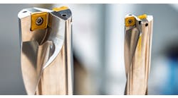
Indexable Carbide Drills — Indexable drilling has become so efficient and cost-effective that in many cases it is less expensive to drill the hole than to cast or forge it. Basically, the indexable drill is a two-fluted, center-cutting tool with indexable carbide inserts. Indexable drills were introduced using square inserts. With indexable drills using the more popular Trigon insert, two inserts are used; but as size increases, more inserts are added with as many as eight inserts in very large tools.
Indexable drills have the problem of zero cutting speed at the center even though speeds can exceed 1,000 SFPM at the outermost inserts. Because speed generally replaces feed to some degree, thrust forces are usually 25 to 30 percent of those required by conventional tools of the same size. Indexable drills have a shank, body, and multi-edged point. The shank designs generally available are straight, tapered and number 50 V-flange.
The bodies have two flutes that are normally straight but may be helical. Because no margins are present to provide bearing support, the tools must rely on their inherent stiffness and on the balance in the cutting forces to maintain accurate hole size and straightness. Therefore, these tools are usually limited to length-to-diameter ratios of approximately 4:1.
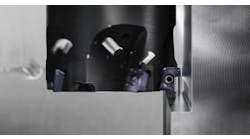
The drill point is made of pocketed carbide inserts. These inserts are usually specially designed. The cutting rake can be negative, neutral or positive, depending on holder and insert design. Coated and uncoated carbide grades are available for drilling a wide variety of work materials. Drills are sometimes combined with indexable or replaceable inserts to perform more than one operation, such as drilling, counterboring and countersinking.
Body-mounted insert tooling can perform multiple operations.
The overall geometry of the cutting edges is important to the performance of indexable drills. As mentioned earlier, there are no supporting margins to keep these tools on line, so the forces required to move the cutting edges through the work material must be balanced to minimize tool deflection, particularly on starting, and to maintain hole size.
While they are principally designed for drilling, some indexable drills can perform facing and boring in lathe applications. How well these tools perform in these applications depends on their size, rigidity and design.
When used under the proper conditions, the performance of indexable drills is impressive. However, the manufacturer's recommendations must be carefully followed for successful applications.
Trepanning — In trepanning the cutting tool produces a hole by removing a disk shaped piece also called slug or core, usually from flat plates. A hole is produced without reducing all the material removed to chips, as is the case in drilling. The trepanning process can be used to make disks up to 6" in diameter from flat sheet or plate. A trepanning tool also called a Rotabroach.
Trepanning can be done on lathes, drill presses and milling machines, as well as other machines using single point or multi-point tools. Rotabroach drills provide greater tool life because they have more teeth than conventional drilling tools. Since more teeth are engaged in the workpiece, the material cut per hole is distributed over a greater number of cutting edges. Each cutting edge cuts less material for a given hole. This extends tool life significantly.
Trepanning Operations — Trepanning is a roughing operation. Finishing work requires a secondary operation using reamers or boring bars to get a specified size and finish. Of the many types of hole-making operations, it competes with indexable carbide cutters and spade drilling.
Several types of tools are used to trepan. The most basic is a single- or double-point cutter. A hole saw is another tool that trepans holes.
Cutting Tool Material Selection — M2 High Speed Steel (HSS) is the standard Rotabroach cutting tool material. M2 has the broadest application range and is the most economical tool material. It can be used on ferrous and non-ferrous materials and is generally recommended for cutting materials up to 275 BHN. M2 can be applied to harder materials, but tool life is dramatically decreased.
TiN-coated M2 HSS Rotabroach drills are for higher speeds, more endurance, harder materials or freer cutting action to reduce power consumption. The TiN coating reduces friction and operates at cooler temperatures while presenting a harder cutting edge surface. TiN-coated tools are recommended for applications on materials to 325 BHN.
Carbide cutting tool materials are also available as a special option on Rotabroach drills. Carbide offers certain advantages over high-speed steel. Applications are limited and need to be discussed with a manufacturer's representative.
Rigidity and Hole Size Tolerance — Rotabroach drills were originally designed as roughing tools were originally designed as roughing tools to compete with twist drills and provide similar hole tolerances. Many users have successfully applied Rotabroach drills in semi-finishing applications, reducing the number of passes from two or more to just one. A rigid machine tool and setup are required to produce holes to these specifications. Tolerances will vary with the application and are impossible to pinpoint.
Chip Control — In material such as aluminum, tool steels and cast iron, proper selection of feeds and speeds usually causes the chips to break up and allows them to be flushed out of the cut by the cutting fluid. In many other materials, such as mild and alloy steels, the chips tend to be long and frequently wrap themselves around the drill to form a "bird's nest." In most manual operations this is an annoyance that is outweighed by the other benefits of the method. In automated operations, however, the build-up of chips around the drill cannot be tolerated. Besides the obvious problems that this can cause, the nest of chips impedes the flow of additional chips trying to escape from the flutes. This in turn can cause the flutes to pack and may result in drill breakage.
There are several methods that can be used to break up the chips if this cannot be accomplished by adjusting the feeds and speeds. One method is to use an interrupted feed cycle. It is recommended that the drill not be retracted as with a "peck" cycle, because chips may become lodged under the cutting edges. Instead employ an extremely short dwell approximately every two revolutions. This will produce a chip that is usually short enough not to wrap around the tool. A programmed dwell may not be necessary since some hesitation is probably inherent between successive feed commands in an NC system.
Advantages of Trepanning Tools — The twist drill has a center point, which is not really a point at all. It's the intersecting line where two cutting edge angles meet at the web of the drill. This point is the so-called "dead zone" of a twist drill.
It's called a dead zone because the surface speed of the cutting edges (a factor of revolutions per minute and diameter of the drill) approaches zero as the corresponding diameter nears zero. Slower surface speed reduces cutting efficiency and requires increased feed pressure for the cutting edges to bite into the material. In effect, the center of the drill does not cut-it pushes its way through the material. The amount of thrust required to overcome the resistance of the workpiece often causes the stock to deform or dimple around the hole, and creates a second problem-burrs or flaking around the hole's breakthrough side. As material at the bottom of the hole becomes thinner and thinner, if the feed is not eased off, the drill will push through, typically leaving two jagged remnants of stock attached.
Trepanning tools produce holes faster than more conventional tooling. In the illustration below is a 1 1/2" hole drilled into a 2"-thick 1018 steel plate with: a spade drill, with a twist drill, with an indexable carbide drill, and with a Rotabroach. With approximately 50 to 80 percent faster drilling time, the cost per hole can be substantially lower.
George Schneider, Jr., is the author of Cutting Tool Applications, a handbook to machine tool materials, principles, and designs. He is the Professor Emeritus of Engineering Technology at Lawrence Technological University, and former Chairman of the Detroit Chapter of the Society of Manufacturing Engineers.
