Mark Grizotsky proposes the following concept for machining precision thin slot and surface under angles:
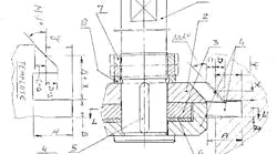
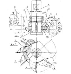
“There are times that we need to perform precision machining for thin slot and surface under-angles, with dimensions X and Y from the slot. See the sketch of the set.
“On the mandrel (1) we install a milling cutter (2) with a single-angle necessary to us. The cutter is standard, with standard cutting angles.
“Also on the mandrel (1) we install milling cutter (3) and milling cutter (4), with cotter (5) and adjusting ring (6), and ring (8).
“Two nuts (7) keep the cutters (2, 3, and 4) on the mandrel as well. The mandrel is installed in spindle of the milling machine.
“Two cutters (3 and 4) have a special design method, which is known as “tooth behind tooth, MLG”. The meaning of this is that between the teeth of cutter (3) must be located the teeth of cutter (4). After the teeth of cutter (3) are located the teeth of cutter (4).
“For example, between four teeth of cutter (3) are located four teeth cutter (4), and the teeth of cutter (3) are located behind the teeth of cutter (4). When we place ring (6) between (3) and (4), we increase the size of the slot and we have material for grinding the left side tooth of cutter (3) and the right side tooth of cutter (4), of which are wear before in milling operation. When grinding is finished we can receive size of the slot, and start the milling operation.
“For grinding a set assembly of teeth edges we need to use a template with dimensions A, B, C, D, X, Y, and angle M, on the grinding pantograph machine, but the template is one we can produce on the “Loewe” optical grinding machine.“
