Our correspondent writes with the new report of the following innovation:
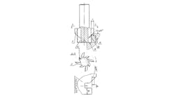
“Some times we have the need to machine three plane surfaces — A, B, and C. Surface A is perpendicular to Surface B, and Surface C will have an angle (M) to Surface B with two dimensions, D and E. (See sketch.) Cases such as this happen very frequently in precision machining.
“In this situation, we have discovered that we can use a special milling cutter that may be used on the vertical or horizontal milling machine.
“The teeth of the cutter have standard cut edge angles. But, these teeth also have the same particularity.
“Each cutter has eight (8) teeth, with four (4) teeth (K) that are used to mill surfaces A and B; the edges of these teeth are perpendicular.
“Also, each cutter has four (4) teeth (F) with an angle (M) and two dimensions, D and E.
“The two teeth profiles, K and F, follow one after the other (so that the teeth of one type pass through the teeth of the opposite type.
“To grind these teeth (both new teeth and those that have shown wear) we need to use a template on a grinding machine with a pantograph system.
“But, the template is one we can produce on the “Loewe” optical grinding machine.”
About the Author
Mark Grizotsky
Owner
Mark Grizotsky, owner of MLG Tool Design in Willowdale, Ontario, has been a major contributor and influencer to machinists everywhere with his insights to machine design and set-up, tooling design and selection, and advice for preparation and processes.
