By Dennis King
Director of Engineering, Command Tooling Systems LLC (www.commandtool.com)
Edited by Jim Benes
Associate Editor
Predicting the service life of a toolholder is extremely difficult.
However, understanding and avoiding the factors that shorten the life of various types of toolholders can maximize their life spans. Quality toolholder shanks are straight within about one ten-thousandth of an inch, round within millionths and have the ability to cut accurately within a couple of ten-thousandths of an inch.
Unlike tools on turning machines that typically are fixed, tools on machining centers are being changed constantly. Because the positioning of tools is a function of the fit between the toolholder and the spindle, positioning tools accurately on machining centers is a process that has a tendency to break down. Dirt, chips and wear will begin to affect this connection over time.
Tool shanks should be inspected frequently for signs of wear that include marks, dents and contamination such as imbedded chips. Tools that show visible signs of degradation should be replaced. Also, a taper measuring device should be used to ensure a proper fit between the taper and spindle.
Different types of toolholders react differently to cutting forces so frequent inspection is important.
End mill toolholders usually are subjected to significant side loads. Over time, the inside diameter of toolholders used for end mills tends to bell mouth. When this becomes excessive, the toolholder should be replaced. End mills try to pull out of the spindle. This can cause fretting corrosion on the toolholder taper from the constant pounding of the cutting action and is evidenced by a copper sheen on the tool shank. Holders that exhibit this wear pattern also should be replaced. Side lockscrews should be inspected routinely and replaced as required.
Shrink-fit holders are used like end mill holders and share the same concerns. Additionally, these toolholders require heat to engage the cutter shank. Toolholders manufactured by quality suppliers are made from H13 tool steel or an equivalent alloy. This steel is tempered at 1,070 degrees F. If the toolholder is heated in excess of this temperature during the insertion or removal process, it is ruined. Toolholders that are overheated should be replaced.
Collet chucks normally are used to hold drills. Because the cutting forces during drilling are back toward the spindle, fretting corrosion is not an issue. However, collet seats should be inspected for wear and galling in the same manner as the taper shank. The nose also should be checked for cracks that can be caused by collisions or over tightening of collet nuts. Additionally, nosepieces should be examined for broken extractor ears.
Shell mill adapters can develop excessive wear on drive keys and lock screws. Replace those that have visible damage and inspect tool shanks for fretting corrosion, galling and other abnormalities.
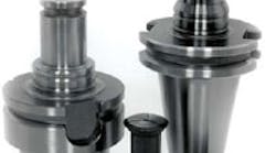
Retention knobs are the critical pieces that hold the tool in the spindle. These components are subjected to significant forces that include tightening torque, pull from the drawbar and, when end milling, the pull from the cutting action. Retention knobs should be inspected frequently and replaced every two years in normal use.
Excessive tightening of retention knobs can result in taper bulging that contributes to taper/spindle misfit. This can also lead to retention knob failure.
| Recommnded retention knob installation torque | |
| Taper size | Installation torque (ft-lb) |
| 30 | 8 |
| 40 | 30 |
| 45 | 50 |
| 50 | 75 |
| 60 | 120 |
The pulling force of a drawbar directly influences the performance characteristics of the tool-to-spindle connection. During a tool change, the force deforms the mating tapers elastically until enough surface contact is made to distribute point contact forces and seat the taper. Performance characteristics that are dependent on the drawbar pull force include the positional accuracy of the system, the connection’s resistance to torque slippage, the resistance to pull out due to heavy cuts and the vibration that can cause damage to taper mating surfaces. Drawbar pull force always should be adjusted to the manufacturer's specifications.
| Suggested drawbar pull force | |
| Taper size | Drawbar pull force (lb) |
| 30 | 1,200 |
| 40 | 2,300 |
| 45 | 4,000 |
| 50 | 5,000 |
| 60 | 13,000 |
Drawbar pull forces should be checked periodically with a drawbar dynamometer, and the mechanism should be adjusted as required.
Shrink-fit technology to hold cutting tools has become common with the advent of modern induction heating units. The advantage over conventional toolholding methods is greater gripping power and improved concentricity.
Theoretically, gripping pressure is a function of the interference between the bore, the tool shank and the wall thickness of the holder. The damping pressure for carbide shanks is approximately 10 percent less than an equal size steel cutting tool because of the difference in Poisson’s ratio (a measure of the tendency of a sample of material, when stretched in one direction, to get thinner in the other two directions).
Pullout force is a function of the gripping pressure, the coefficient of friction and the contact surface area. Typical calculations for pullout force use a coefficient of friction of 0.15 and assume a surface finish of between 12 μin. and 16 μin. on the wall of the holder and 8 μin. on the tool shank. Tests with steel on steel with a finish on both parts at about 16 μin. confirm the calculations.
Pullout force is proportional to the friction coefficient. Thus, a carbide tool with a better finish would pull out with less force than calculated with a coefficient of friction of 0.15. For this reason, superfinished carbide shanks on high helix cutters will pull out under heavy cuts or chatter. That is the reason that tool shanks should not have a finish finer than 16 μin. for optimum holding power.
Tool shanks should be round, without flats, raised engraving, dents or other surface imperfections. Also, cutting tool shank diameters must be held within a tolerance of h6.
| Tool shank diameter tolerances to meet an h6 tolerance level | |
| Shank Size, in. (mm) | Tolerance, in. (mm) |
| 0.236-0.394 (6-10) | -0.00035 (-0.009) |
| 0.394-0.709 (10-18) | -0.00043 (-0.011) |
| 0.709-1.181 (18-30) | -0.00051 (-0.013) |
| 1.181-1.968 (30-50) | -0.00063 (-0.016) |
Cleaning of mating parts is essential. Oil turns to sludge during the heating process, and can effectively “glue” the components together. A nonflammable solvent should be used to clean mating parts. Expanding gasses from moisture trapped behind the tool can create high pressures during tool removal.
