Calculating Strength of Materials for Spline Bush with External Gear Teeth on Standard Splined Fittings with Straight-Sided Splines
Sometimes a tool designer must calculate the size and dimensions for a spline bush (ring) with external gear teeth if he sees large external forces (F), torsional moment (M), and bending moments (M1, M2). We offer here a short, rough calculation.
1. Determine the inside diameter (d) of the spline shaft maximum, which is 112 mm, z = 10 notes the number of the spline from standard European JIS B 1601.
2. This inside diameter (d) can transfer power (P), transmitted in kwt by the following formula: :
d = 12x ∛P/n (1)
P= nxd 3/1728 (2)
P = 162 kwt, n = 200 rpm.
3. We take P = 162 ktw for calculation.
4. Now, we determine torsional moment at which the spline shaft transfers
M = 97400 x P/n (3)
M = 78894 kg.cm
5. Determine the torsion stress (ST)
ST = M/W (4)
W = 0.2 x(d3) (5)
where W is the moment of resistance of torsion
ST = 281 kg/cm2 that is allowable.
6. Determine the forces on the splines:
N = M/(r x z) (6)
r = d/2 = 112 mm/2 = 56 mm = 5.6 cm
N = 97400/(5.6 x 10)
N = 1739.3 kg
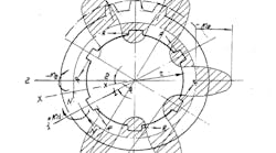
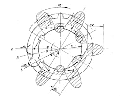
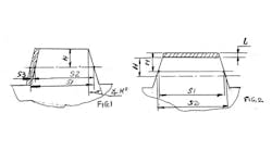
7. Now, we calculate the bending moments in the intersection between the spline (M1) and the spline (M2). See Figure 1.
For M1 = M x [(1-z/3.1416 x sin(3.1416/z)] x1/z (7) – MLG -7
For M2 = M x [cos(3.1416/z) – z/3.1416 x sin(3.1416/z] x 1/z (8) – MLG -8
For z = 4, M1 = + 0.025xM, M2 = -0.048xM
(9) — MLG - 9 (10) — MLG – 10
For z = 6, M1 = +0.008xM, M2 = -0.014xM
(11) — MLG - 11 (12) — MLG - 12
For z = 8, M1 = +0.003xM, M2 = -0.007xM
(13) — MLG - 13 (14) — MLG - 14
For z = 10, M1 = +0.0016 x M, M2 = -0.0033xM
(15) — MLG - 15 (16) — MLG - 16
For z = 16, M1 = +0.0008 x M, M2 = -0.0005xM
(17) — MLG - 17 (18) — MLG – 18
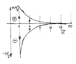
See Figure 2.
We see that with M1, with (+) sign, and M2, with (-) sign, indicates that variable moments + M1 and -M2 are cause of the pitting on the splines. As we see more z than less moments on the splines, and this must be taken into account by the tool designer.
8. The next step is to use the theory of curved beams. Calculate the stresses of curved rectangular cross sectional area of the spline bush ring.
9. The next step is to calculate the bending stress in the gear teeth on the outside diameter of the spline bush ring using reference books for details of the machines.
10 If all the stresses are allowable you can start your tool designing process. If you are not satisfied with the stresses, you can make the following changes:
a. Material and hardness (Rockwell or Brinell hardness scales);
b. More changes to cross-sectional area parameters;
c. Reduce the load;
d. Increase the outside diameter; or,
e. Increase the pitch or module of the gear teeth.
