Influences of Wear on Cutting Tools and Deflection of the Shaft Under Cutting Force on the Sizes of Holes, Slots, and Cotter
Wear depends on a lot of factors, especially time, as illustrated in Figure. 1. Variable forces during the cutting process also influence wear – and the more forces are at work inducing more wear to the tool. In this article, we show difference sketches of wear.
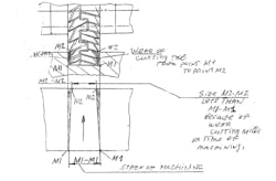
When we machine a slot by a set of two disk cutting milling tools we start from points M1 and finish on point M2. And, we see as a direct line M1M2 under angle M:
tanM = W/L — formula TU.RO.MI. -1
where
W = wear from one side
L = way of one operation
As we see, the distance of M2-M2 is less than M1-M1 on the wear of cutting tools in machining. This means that machining must be under control. Wear is happening inside of the cutting tool.
Figure 2 shows the machining of a slot.
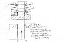
Figure 3 shows that a bon or cotter will have more size on the machining end because of the wear.
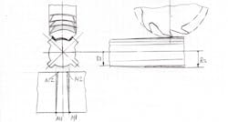
In Figure 4, we see machining or grinding of a slot on the shaft by the radius of cutting mill with two symmetrical angles.
The picture shows that on the end of L the radius on shaft R2 is more than R1 from the start because of wear, and we have a distance between the slots on the start of M1-M1 more than the size of M2-M2 on the end of finish L of machining because of wear going to the inside of the cutting tool.
TanM = (R2-R1)/L, or
Arc Tan(R2-R1)/L=angle M-formula DU.IL.MI-2
As we see, we have different combinations of wear, and tool designers must take this into account where the machining process also starts to work as a force of the cutting tool, located between the shaft and cutting tool. This will cause the shaft to sag, increasing the inside diameter of the shaft and increasing the thickness of splines on the spline shaft (see Fig.5).
The formula for cutting force is available in published references. A well-known formula for maximum deflection is
f = (Px L3)/48xExI -- formula FI.PI - 3
where
P is the cutting force
L is the distance between supports for the shaft of the milling machine
E is the modulus of elasticity of the material of the shaft.
I is the moment of inertia of the cross-section of the shaft diameter.
Tool designers may find E and I defined by a reference of the strength of the material.
About the Author
Mark Grizotsky
Owner
Mark Grizotsky, owner of MLG Tool Design in Willowdale, Ontario, has been a major contributor and influencer to machinists everywhere with his insights to machine design and set-up, tooling design and selection, and advice for preparation and processes.


