By Mary Kay Morel, Staff Writer/Editor, Motoman Inc.
Edited by Bruce Vernyi, Editor-in-Chief, American Machinist
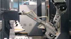
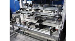
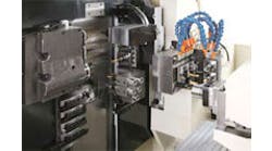
Shows the robot reaching in one of the CNC machines. The robot then moves to the correct table, and places the fixture on the table.
Applied Engineering, Inc. (www.appliedeng.com) of Yankton, S.D., produces precision machined aluminum components and assemblies for a broad range of applications in aerospace, defense and commercial applications.
The company prides itself on innovation and use of cutting-edge automation to produce high-quality products, delivered on time, at the lowest achievable cost. It is ISO 9001, AS9100 and NADCAP certified, and it accomplishes these goals by applying flexible machining centers that provide lights-out, unattended operations.
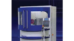
Applied Engineering implemented a unique robotic machine tending system in 2006 that uses a six-axis, Motoman HP20 robot that is invert-mounted from a 20-m (65.6-ft) long overhead rail system. The HP 20 robot loads and unloads four LeBlond Makino A55 horizontal machining centers and eight 180-degree indexing turntables to provide continuous operation.
Each indexing turntable can hold two to 30 parts on each side, along with the fixtures and grippers that are required to handle the parts. End-of-arm tool change is automatic for the robot.
As many as four parts can run at the same time, but 12 others can be waiting to run after those are complete. A part can be located in any one of 30, programmed positions on each table.
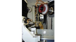
Additionally, Table 8 can be configured as a drilling and countersinking station, and can be used for precision drilling, to provide additional capability and flexibility.
The invert-mounted, six-axis Motoman HP20 robot traverses the overhead rail to load/unload individual parts from the indexing turntables into or from two operations in each of the machining centers. The robot returns parts to the same turntable from which they were picked. It is a very busy system, and the fact that not every part the company makes can run in every CNC adds to the programming complexity.
The robot checks each part to verify that it can run in a particular machine.
When the robot has loaded the part into Op 1 of a machine, it scans to see if any other machining centers are done. The robot unloads finished parts from machines, and places them in their target destinations in finished parts bins on one of the indexing tables.
The robot returns to the machine it loaded, and transfers a part from Op 1 to Op 2. Then it scans the indexing tables, and gets another part to place in Op 1.
The process repeats, with the robot loading and unloading each of the four machines (and/ or the drilling station at Table 8), as needed.
An Allen-Bradley SLC/505 PLC controls I/O communications between the CNC machines, tables and the robot. The system is unique because it does not use an end-of-arm tool or sensor I/O to tell the robot which gripper or fixture it has.
Instead, that information is stored in the programs as variables, so the robot knows the operation it has completed. This approach saved Applied Engineering a lot of I/O, as well as the associated expense of complex grippers, multiple sensors and additional wiring.
“What makes this rail-mounted robotic machine tending system even more unique is that programs are automatically generated off-line to accommodate a nearly infinite variety of part variations,” Dave Brinkman, engineering manager at Applied Engineering, said.
Using an Excel spreadsheet, the load/ unload program is modified by changing part dimensions. It enters the indexing table that the robot needs to pick from, the target machine, and the finished part destination.
Many of the robot moves in each program “recipe” have been consolidated into “macros” which greatly simplifies the programming code. Applied Engineering manually loads programs into the robot controller using compact flash cards. Little manual programming is required to touch-up new programs prior to running them.
MotoSIM EG off-line programming software and MotoSIM Points Importer with G-Code Converter software is used to program the drilling/countersink station at Table 8 off-line.
CNC programs written in G-code are translated into robot programs that are ready to run. This allows a less expensive and more flexible six-axis robot to perform precision tasks that once could only be performed using a multiaxis CNC machine.
For more information, contact Motoman Inc. (www.motoman.com), or at 937-847-6200.
