This is the third and final report in a series, Selecting, Configuring and Lubricating Tapered Roller Bearings for High-Speed Machine Tool Spindles.
The first installment is Selecting Tapered Roller Bearings for High-Speed Machine Tool Spindles.
The second installment is Configuring Roller Bearings for High-Speed Machine Tool Spindles.
The speed capability of a 2TS-IM spindle is determined by the bearing selection, mounting configuration, and the type of lubricant and lubrication system. The lubricant and lubrication systems influence the heat-generation and heat-dissipation rates, and thus are important to determining the speed capability of the spindle. This report will provide guidelines for understanding the speed ratings of TRBs, grease selection and run-in procedures and oil lubrication and circulation systems.
Understanding TRB speed ratings
The speed rating of any bearing is relative to its size, and is inversely proportional, i.e., the larger the bearing size, the lower the speed rating. Tapered roller bearings (TRB) are no exception to this rule. However, the method of characterizing the speed is different from other bearing types.
To take the bearing size out of the equation, an equation has been developed to normalize the speed based on the size of the bearing. This is done for ACBBs and CRBs using the dN value that is equal to the bearing bore in millimeters multiplied by the speed and RPM. A bearing with a 10-mm bore running at 100,000 rpm will have the same dN value as a bearing with a 1,000-mm bore running at 1,000 rpm: both are equal to 1,000,000 dN. Speed guidelines are based on dN, not RPM.
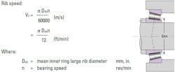
TRB's speed guidelines are based on the rib speed of the bearing, not the dN value. The rib speed is simply the linear velocity of the elliptical rib-roller contact. It is calculated using the midpoint of contact between the roller large end and cone rib, Dm, and the bearing speed in RPM (see Figure 1.) Dm value can be scaled from a drawing or approximated as the average of the bearing bore and OD.
When the rib speed begins to approach 5 meters per second (1,000 fpm) the heat generation can become significant. If the heat cannot be removed efficiently, it can result in the breakdown or loss of the lubrication film and cause surface-initiated damage that can significantly reduce the spindle’s performance and service life. Timken provides speed guidelines for 2TS-IM spindles using grease or oil for rib speeds up to 4,000 fpm (20 m/s; see Table 1.)
There are no clear-cut speed limitations for TRBs since it depends on the bearing design and lubrication system. The guidelines provided in Table 1 are based on typical industrial experiences relating to speed and temperature for various types of lubricating systems for optimized bearings and spindle configurations. Testing is always recommended for all new high-speed applications.
TRB grease selection, run-in guidelines
Grease lubrication has several advantages over oil lubrication and the greatest is system design simplicity, followed by cost. However, grease-lubricated bearings are limited in speed because all the heat they generate must be carried away by conduction through the shaft and housing. They also require a break-in procedure that distributes the grease while thermally stabilizing the bearings, which can be a time-consuming process depending on the maximum spindle speed.
A conventional polyurea or lithium NGLI 2 grease with medium-to-low viscosity mineral oil can be used for rib speeds up to 1,000 fpm (5 m/s.) At this speed, an initial grease fill of 30 to 50% of the free space in the bearing can be used. Conventional mineral oil greases have been successfully used with spindles running up to 2,000 fpm (10 m/s), but special attention to the bearing selection, spindle configuration, and grease fill were required.
It is suggested to use a high-speed synthetic grease for TRB spindles with rib speeds above 1,000 fpm (5 m/s.) There are many synthetic and synthetic-blend greases available for high-speed machine tool spindles. Work with the bearing and grease supplier to select one that is optimized for the application. It is possible for tapered roller bearings lubricated with high-speed synthetic grease to achieve rib speeds of 2,500 fpm (12.5 m/s.) Thermal stabilization has even been achieved at speeds up to 4,000 fpm (20 m/s) under ideal conditions.
A deliberate run-in procedure is required for a 2TS-IM machine tool spindle with synthetic grease to successfully achieve thermal equilibrium. After initially filling 15 to 30% of each bearing’s free volume with grease, start at a reasonable low speed, typically 10% of the maximum operating speed, and let run 10 to 15 minutes.
Next, increase speed to 25% of the maximum speed until a stable temperature is reached. Thermal stability is typically accepted when a bearing temperature that holds to +/-5˚F (2.5˚C) for 15 minutes. It is important to time-trend the bearing temperatures, which will help in visually monitoring the progress of the run-in. Bearing temperatures should not exceed 100˚F (55˚C) above room temperature or a maximum temperature of 70˚C (160˚F.) These temperatures risk possible permanent grease or bearing damage.
When stability is achieved, increase the speed to 50%, followed by 75% and finally 100%. Smaller increments can be chosen based on the maximum spindle speed. If stability is not achieved, then the spindle bearings should be allowed to cool to room temperature and restart procedure at the last speed where stability was achieved. If after a repeated attempt thermal stability is not achieved, it may be necessary to remove some grease from a bearing before making a third attempt. A bearing with excessive grease fill may never stabilize. Experience has shown that stabilized temperatures, around 30˚ to 35˚F (15˚ to 20˚C) above ambient can be obtained at the maximum permissible speed.
- Following here are a few tips for 2TS-IM machine tool spindles when using grease to lubricate the bearings:
- It is not recommended to wash the bearings prior to installation. The rust preservative is compatible with most machine tool greases and oils. Grease can be applied to the bearing.
- A very small initial quantity of grease is applied to prevent excessive churning.
- Initial run-in period to evacuate unnecessary grease from the bearing.
- Good spindle design to retain grease around the bearings.
- Efficient sealing to protect against external contamination.
When using synthetic greases, the limiting factor will be the regreasing interval or the grease life when the "lubrication for life” concept is used (no re-greasing.) Depending on load and speed conditions, the grease life typically will be limited to 5,000-8,000 hours. It is suggested to review the application with the grease supplier for a more accurate estimate of grease life.
TRB oil lubrication and circulation system
Grease lubrication is generally preferred over oil due to its simplicity and cost. However, grease is limited by both load and speed. Spindles with oil circulation systems can remove both heat and debris during operation, plus deliver the oil at a much lower temperature. Because viscosity is inversely proportional to temperature, the lube oil delivered from a circulation system will have a higher viscosity when compared to that of the base oil of a grease due to the difference in temperatures. This is helpful for applications with higher loads to ensure the lube film thickness provides adequate separation between the rollers and raceways.
Finally, spindles with oil circulation systems do not require a run-in procedure that is necessary with greased spindles because the oil drains away as quicky as it is delivered.
Most oil-lubricated machine tool spindle applications use some form of forced circulation system whether it is an air/oil system of an oil feed/jet system due to the positioning/movement of the spindle on the machine. Oil baths can be used on spindles that are stationary, such as headstock and tailstock spindles on horizontal lathes. The focus here is on an oil feed/jet system because this is the most common and practical means of delivering oil to the bearings.
Whether designing or maintaining a spindle with a forced-lube oil system, it is important to understand the parameters that are considered when sizing and configuring an oil circulation system. Following is a list of these parameters:
- Physical and chemical properties of the oil
- Pump size / flow rate
- Heat removal / exchanger size
- Filter / filtration level
- Reservoir size and location
- Porting of the oil to the bearings
- Number of injector points
- How to scavenge the oil after exiting the bearings
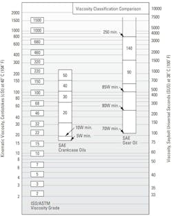
When selecting a lube oil, it is important to know that there are several classifications of oils based on viscosity grades. The most familiar are the Society of Automotive Engineers (SAE) classifications for automotive engine and gear oils. The American Society for Testing and Materials (ASTM) and the International Organization for Standardization (ISO) have adopted standard viscosity grades for industrial fluids. Figure 2 shows the viscosity comparisons of ISO/ASTM with SAE classification systems at 40° C (100° F.)
The lube oil is typically selected based on its viscosity, or resistance to shear/flow. Higher viscosity oils produce a “thicker” film that separates the raceways and rollers during operation and help to prevent metal-on-metal contact that leads to surface-initiated damage of the bearing.
However, increasing the oil viscosity also increases the heat generation from the bearing, which increased the torque/drag and operating temperature. It is necessary to select an oil with a viscosity that balances these two diametrically opposing characteristics.
Machine tool spindles contain precision-class bearings with finely honed rollers and races. This results in very low surface roughness (small asperities) that require a thinner separating film compared to a standard-class bearing. This results in a lower viscosity requirement for the lube oil. An oil with an ISO viscosity grade of VG10 to VG32 is common for TRB spindles that run at rib speeds greater than 2,000 fpm (10 m/s), while slower spindles with higher loads may be as high as a VG46 to VG68. Analysis of the spindle is the best way to determine the correct viscosity grade.
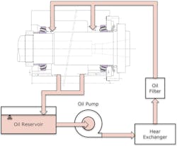
A force-fed oil lubrication system is simple in design, with oil pumped from a reservoir through a heat exchanger, followed by a filter, and then injected into each bearing separately. Upon exiting each of the bearings, the oil makes its way through drain passages that guide it back into the reservoir (see Figure 3.) The flow rate of the pump is based on the total heat load of the system, and must include the spindle bearings plus any other points of lubrication that share the oil, such as other bearings and gears on the machine. The heat exchanger is the preferred method of removing heat from the system that helps to regulate the running temperature of the oil. The maximum particle size allowed by the oil filter should be less than 40 μm (0.0015 in.), preferably 25 μm (0.0010 in.) or less.
Oil is introduced at the small end of the rollers and drained away at the large end to take advantage of the natural pumping action of tapered roller bearings. Experience has shown that axial oil jets should be positioned to direct oil at the small end of the roller at the gap between the cage and the inner ring (see Figure 4.)
For high speeds, or in case of large-size bearings, three or more oil jets can be arranged about the circumference to better distribute the oil within the bearing more evenly.
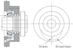
An effective circulating oil system requires adequate drainage to prevent an oil buildup that would cause excessive churning and unnecessary heat generation. Oil passing through a high-speed bearing will exit the bearing at a high velocity and will swirl around the housing in the direction of rotation of the bearing. To effectively drain the oil away, the high velocity must be slowed, and the swirling action stopped so that the oil will collect in the drain area. A drain catch basin is required to break up the flow of oil and direct the oil to the drain hole (see Figure 5.)
Oil drain sections must be adequately dimensioned to ease the rapid evacuation of the oil.
Regardless of whether you are designing a forced-oil circulation system or maintaining them in a production environment, it’s important to understand the theory of operation. Following is a list of questions that need to be answered when designing or troubleshooting a system:
- Was a high-quality mineral oil, or synthetic oil, with the appropriate viscosity for the loads and speeds of the application selected?
- Is there an adequate supply of oil for both cooling and lubrication?
- Is the reservoir large enough to prevent premature oil deterioration?
- Is there metered control of the quantity of oil delivered to each bearing?
- Do the oil-filter(s) meet the suggested filtration level?
- Are the oil jets ported properly to deliver lubricant to the small end of the bearing?
- Is the flow rate of the oil pump and heat exchange adequate to handle the heat load of the spindle and any other components that share the lube oil?
- Is the drain size adequate to remove excess oil from the bearing cavity?
Conclusion
When the loads and speeds in the duty cycle of a machine tool spindle are positioned between what ACBBs and NN30 CRBs can handle, a TRB is most likely the optimal solution. This is due to TRBs’ unique combination of load capacity, speed rating, and the simplicity of a two-bearing solution. This positions them well for both milling and turning applications. Because the TRBs operate with a true “on apex” rolling motion and can take a combination of radial and axial loads, they are a popular choice for many industrial applications.
Because tapered roller bearings are available in four precision classes, there are many designs suitable for machine tool applications. Designing and maintaining TRB machine tool spindles requires a good understanding of the features presented in this series, including bearing geometry, the features that are controlled by the precision classes, rib speed limits, lubrication methods, and part numbering. Providing that bearing seats meet the suggested geometric form and tolerance, and achieving the proper preload setting are essential to achieving optimal performance.
There are many different types of machine tool spindles for many different applications. Having another bearing type available gives the engineer another potential solution, regardless of whether you are designing a new spindle or overhauling an existing spindle that needs to be repaired.
It is worth noting that the information presented in this series is intended to provide an understanding of how bearings are selected, mounted, and lubricated for machine tool spindle applications. You should always consult with the bearing supplier to get a formal review of the application to validate the bearing selection, provide bearing seat tolerances, bearing setting, and make a lubrication recommendation.
This is the final report in a series, Selecting, Configuring, and Lubricating Tapered Roller Bearings for High-Speed Machine Tool Spindles.
The first installment is Selecting Tapered Roller Bearings for High-Speed Machine Tool Spindles.
The second installment is Configuring Roller Bearings for High-Speed Machine Tool Spindles.
