This is the second report in a series. The first installment is Selecting Tapered Roller Bearings for High-Speed Machine Tool Spindles
Upon selection of the bearings with the appropriate capacity, stiffness, speed capability, accuracy and heat generation for the application, a spindle must be designed to accommodate these bearings to realize their full potential. Whether an LL or L inch series bearing has been selected, or a metric J-type or J-line series, the spindle must provide the proper bearing fits – including the geometric form tolerances, the correct mounted setting, and adequate lubrication.
Following here is a summary of the necessary guidelines that can be used when designing a high-speed machine tool spindle that uses precision-class TRBs.
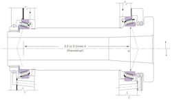
The most common spindle TRB configuration is the 2TS-IM (two opposing single row TS or flanged TSF single row bearings, indirectly mounted), as shown in Figure 13. This design allows easy machining of adjacent parts and is easy to assemble.
The distance between the bearing centers should be 2.5 to 3.0 times the spindle nose bearing bore, which helps to achieve thermal equilibrium during operation and optimizes the moment spindle stiffness for overhung tool loads.
Bearing fits and tolerances
In general, the fitting practice for all bearing types will depend on the precision class, spindle layout, loads, speeds, running conditions, vibration, shaft/housing sections, shaft/housing material, and setting conditions.
In the machine tool industry, where shock and vibration are low, the shaft and housing are both made of steel with heavy walls. It is suggested to fit the cone on the shaft with a light interference ranging from -5 um to -50 um, or more, depending on the bearing size and precision class. The tool or work-end of the spindle should be on the tighter end of this fit-up range; while the drive or non-work-end of the spindle should be biased toward the lighter end of the range so as not to impede too heavily the movement of the cone, to allow for preload adjustment.
The average target cone fit depends on whether it is non-adjustable, adjustable, or floating in the housing. Non-adjustable housing fits are the tightest and used on the tool or work-end of the spindle.
Non-adjustable fits range from slight (-1 to -2 um) to tight (-25 to -50 um.)
On the drive or non-work-end of the spinde the fits may be either adjustable (slightly loose to tight) to allow for setting preload using the cup; or floating (loose to extra loose) to allow the cup to float freely in the housing and not impede axial thermal expansion of the shaft.
Adjustable fits range from -25 um tight to +25 um loose depending on size and precision level; while floating fits are always loose, typically +7 up to +75 um.
Most catalogs provide a fit-up range based on the bearing size and precision class. However, the optimal fit-up will depend on the precision class, spindle layout, loads, speeds, running conditions, vibration, shaft/housing sections, shaft/housing material, and setting conditions.
The total runout of a spindle-bearing-housing system is a combination of the bearing runout and the shaft and housing geometric form.If a bearing is mounted onto a shaft and/or into a housing bore that is not round, the bearing will assume some (if not all) of this condition and perpetuate the error motion when cutting or turning the workpiece.
Therefore particular attention needs to be paid to the design and accuracy of the mounting surfaces as toleranced in Figure 14. Note that the cylindricity refers to the radius: When measuring two points of the shaft diameter or the housing bore, the cylindricity tolerances have to be doubled.
The primary function of either the inner or outer race seats and shoulders is to positively establish the location and alignment of the bearing under all loading conditions. It is essential for the bearing seats to be round and square to the adjacent shoulders, spacers, and locknuts. This helps to ensure that the runout is minimized, and it is recommended that the bearing seats should not exceed the values shown in Tables 1 or 2.
The surface finishes of the bearing seats are important in assembly and disassembly of the spindle. They allow for the bearing to be installed and removed easily, and it is recommended to grind these surfaces to prevent micro-asperities from “locking” the ring to the shaft or housing.
Table 2 contains the recommended maximum values for the shaft and housing seats based on the bearing precision class.
Bearing setting guidelines
Accuracy, stiffness, and speed are critical attributes for machine tool spindles that need to be maximized when selecting and installing bearings for those spindles. It is customary to set the bearings in preload as opposed to end play for machine tool spindles because preload removes looseness (play), adds stiffness, and seats the rollers to prevent skidding at high speeds.
However, increasing preload increases heat generation – which for tapered roller bearing spindles is especially critical because that limits your top speed.
To better explain preload, it is important to understand what is happening inside the bearing as the setting transitions from end play into preload. The load zone is the percentage of rollers in contact with both raceways expressed in degrees (~0° to 360°.)
Moreover, the load zone is a function of the bearing’s operational setting. Bearings with mounted endplay (internal clearance) have load zones less than 180°. Bearings with zero mounted endplay (clearance) have a load zone of 180°, and bearings set with a light preload have load zones between 180° and 360°. A mounted setting that yields a load zone of 360° is considered a heavy preload. See Figure 3.
The optimal preload is a balance between minimizing the heat generation and stress versus maximizing the accuracy, stiffness, and speed. Typically, machine tool spindles with a 2TS-IM arrangement set with a line-to-line to light preload (typically 0.000 to -0.050 mm) because during operation the temperature difference between the inner and outer rings yield an increase in the bearings preload due to lateral loss.
The best way to determine the optimal setting is through experience and application analysis. If the spindle is modeled with good temperature estimates based on historical measurements, at the loads and speeds it is to operate under, an optimal preload setting can be concluded based on the results of the analysis.
This is the second report in a series, Selecting, Configuring, and Lubricating Tapered Roller Bearings for High-Speed Machine Tool Spindles.
The first installment is Selecting Tapered Roller Bearings for High-Speed Machine Tool Spindles.
The third and final installment is Lubricating Tapered Roller Bearings for High-Speed Machine Tool Spindles.
