Selecting Tapered Roller Bearings for High-Speed Machine Tool Spindles
The challenge that machine tool builders face when designing spindles for milling machines and lathes is selecting bearings with the optimal balance of speed, load-carrying capacity, stiffness, and precision. These characteristics may be thought of as the four cornerstones of performance for these applications, factors that directly impact the cycle time and part quality. Bearings that can minimize the cycle time and maximize the part quality will directly impact the “bottom line”.
Cycle time is dictated by the material removal rate (MRR) or the amount of material that can be removed per unit time. MRR is impacted by the feed rate of a milling cutter, or the surface speed of a turning insert, both define the linear speed that the tool moves through the material.
The surface speed multiplied by the width and depth of the cut determines volumetric material removal rate. Assuming the cutter/insert or the workpiece material are not limiting factors, the speed, load-carrying capacity, and stiffness of the spindle all impact the cycle time.
The part quality is defined by the accuracy (geometric tolerancing) and the surface finish or “roughness”. The linear and rotational accuracy of positioning the workpiece and cutter play a role in determining these characteristics, however, the spindle is the biggest factor when considering the part quality. The accuracy or precision of the spindle bearings determines the tolerance of the workpiece while the stiffness affects the surface finish.
The surface finish can be affected by chatter, which is a resonance between the natural frequency of the spindle and the sinusoidal excitations of cutting/turning. Increasing stiffness increases the natural frequency and reduces the vibrational amplitude of resonance.
Precision angular contact ball bearings (ACBBs) are the most popular bearing type used in machine tool spindles due to their cost, availability, and speed capability. However, the benefits of their high-speed ratings are offset by lower capacity and stiffness when compared to roller bearings. ACBBs are typically used in duplex sets at the front and rear of the spindle. It is not uncommon to see sets of three, four, or more when the applied cutting and/or drive loads exceed the capacity of a duplex set.
Precision, two-row NN30 cylindrical roller bearings (CRBs) are common in spindles where radial loads become too excessive for ACBBs but speed requirements are modest. Spindles designed for NN30’s have the added complexity of setting the CRBs properly, typically done with fits. They also require ACBBs to carry any thrust loads. Speed also suffers from having four bearing rows at the front of the spindle due to the heat generation.
Precision-class tapered roller bearings (TRBs) offer the spindle designer an option for spindles with load requirements positioned between ACBBs and CRBs. Like the ACBBs, TRBs can handle combined radial and thrust loads, only heavier. Because CRBs are dedicated to handling heavier radial loads, there are applications where these are an optimal solution despite the complexity.
TRB spindles typically consist of only two bearing rows total, whereas ACBBs and CRBs typically have two or more rows at either end. TRB designs offer a 50% reduction in the number of bearings used when compared to ACBBs and CRBs. However, even with a reduction in the number of bearing rows used in the spindle, the heat generation must be considered when designing in TRBs.
This series will provide guidelines for selecting, configuring, and lubricating Precision Class TRBs for high-speed machine tool spindles. The process of selecting the appropriate TRB based on key bearing features that relate to the loads and speeds of the application will be covered first, followed by a review of the appropriate bearing configuration, shaft, and housing fits, geometric form, and setting. Lastly a guide to selecting the appropriate lubricant and lubrication method will be provided.
It is worth noting that the information presented here is intended to provide an understanding of how bearings are selected, mounted, and lubricated. You should always consult with the bearing supplier to validate and finalize these parameters.
Understanding tapered roller bearing design
The fundamental design of TRBs makes them an ideal solution for machine tool applications when heavy cutting or turning loads are applied to the spindle. Understanding some basic principles on how the TRBs operate is key to understanding how to best select an optimum design for the application. When selecting precision class TRBs for machine tool spindles, there are several key features that need to be understood including their basic design & operation, the K-factor, precision classes, and part numbering including the bearing series.
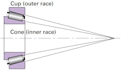
Basic design and operation of TRBs. TRBs exhibit true rolling motion of the rollers on the raceways due to their “on apex” design. The allows for the bearing to run cooler with improved stiffness and accuracy, as shown in Figure 1A.
The true rolling motion is the result of two design features, the taper of the roller and the contact between the spherical surface ground on the large end of the roller and the race rib. When two, single-row TRBs are mounted indirectly as shown in Figure 1B, the optimal spread is when their apexes intersect the shaft centerline at the same location.
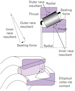
The result is no relative slip between the rollers and raceways ensuring that the surface speeds of the roller and raceways are the same at every point along the roller body. The tapered body of the roller also generates a seating force between the spherical end and the race rib that prevents the rollers from skewing, as shown in Figure 2.
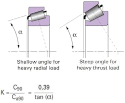
K-Factor. The angled raceways allow the tapered roller bearing to carry combined radial and thrust loads. The half-included cup angle “a” determines the radial and thrust capacity of the bearing and is directly analogous to the contact angle of an ACBB. The K-factor is a means of quantifying the half-included cup angle “a” in terms of radial versus axial capacity. The K-factor is simply defined and the ratio of basic dynamic radial load rating C90 divided by the basic dynamic thrust load rating Ca90 of a single row bearing, or it can be directly calculated from the half-included cup angle as shown in Figure 3.
The smaller the K-factor, the steeper will be the bearing angle and the more biased the bearing is towards thrust versus radial capacity. For example, a bearing with a K-factor less than 1.0 will have a higher thrust versus radial rating, while a bearing with a K-factor greater than 1.0 will have a higher radial versus thrust rating. A bearing’s load rating, speed rating and envelope are the three most important design features when selecting bearings. K-Factors of 1.00 to 1.80 are preferred for machine tool applications where speed is of primary concern.
Understanding TRB precision classes. The technical regulatory associations that control the standards defining bearing tolerance classes are the American Bearing Manufactures Association (ABMA) and International Organization for Standardization (ISO.) ABMA Standard 19.2 controls the precision classes for inch series TRBs while ISO 492 controls them for metric series. The higher the tolerance class, the smaller is the allowable deviation from nominal for specific raceway and ring geometry.
There are three precision-tolerance classes defined by the standards for both metric bearings (P5/C, P4/B & P2/A) and inch-series bearings (3, 0, and 00.) There is also a Timken-specific standard that goes above and beyond the ISO / ABMA tolerances for TRBs that is designated as Precision PlusTM for both inch series (000) and metric series (AA), as shown in Table 1.
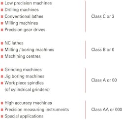
Knowing which precision class to select depends entirely on the application and its specific requirements. Table 2 provides some general guidance for selecting the precision class versus the machine type.
The obvious difference between precision and standard class for any bearing type are the bearing-envelope tolerances (bore, OD, and width) along with the assembled runout of the bearing. However, there are several key bearing design parameters that are not controlled by ABMA 19.2 and ISO 492 that have a significant impact on the bearing’s performance – especially in machine tool applications.
These differences include surface finish, roller profile, and roller-size variation (RSV) all have a notable impact on performance.
Precision Class TRBs have better raceway and roller surface finishes than Standard Class products. Precision Class TRBs are typically set in preload and run at higher speeds. The lower surface roughness of Precision Class TRBs results in lower audible noise and vibration when compared to Standard-Class products.
The roller profile in Precision Class TRBs is designed to yield a 15 to 25% higher bearing stiffness when compared to Standard Class products. The higher stiffness yields a better cut quality and allows the spindle to run deeper cut depths and higher feed rates, resulting in better part finish and higher production rates. The tighter control RSV of Precision Class TRBs results in much lower asynchronous or non-repeatable runout that results in better part tolerances and surface finishes.
TRB part numbering and series
The part-numbering systems for single-row radial tapered roller bearings (type TS) are classified according to metric or inch systems, both are internationally recognized. Inch-system bearings are normally assigned individual part numbers for the inner ring and for the outer ring, whereas ISO (metric) bearings are assigned a unique part number for the bearing assembly, which includes both inner and outer ring.
Within each of these two systems there exists five-part numbering systems, as seen in Figure 4. Because a bearing within any of these systems can be supplied in a precision class it is helpful to understand the differences between them.
Before delving into the numbering systems, it is important to understand what is meant by bearing series. In all the part-numbering systems, the term bearing series is used to describe bearings having the same basic internal geometry (e.g. roller size, inner-ring and outer-ring angles.) Any inner ring (including roller set) can be matched with any outer ring within the same series providing that the same type of bearing is being used.
The original system developed by The Timken Company was based on a family of bearings designed around a common roller. Varying the number of rollers and the angle of the raceways allows different bearings to be designed for predominantly radial loads (shallow angle) or thrust loads (steep angle.) For example, all the tapered roller bearings in the 500 family use the same roller. However, the 595 Series has a steep angle and 24 rollers, while the 525 Series has a shallow angle and 15 rollers. It is not possible to determine any of this information without the bearing print or catalog data.
The current inch part-numbering system was developed by the ABMA to address the expansion in the number of new applications and tapered roller-bearing designs. This part-numbering system has become the international standard for inch-sized bearings and has been applied only to new bearing series designed after its introduction.
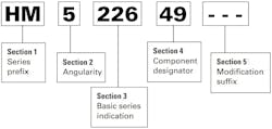
Other part numbering systems also are in use including those based on the original numbering system and proprietary part numbers for special bearings. The ABMA part number is divided into five alphanumeric sections, which are described in Figure 5.
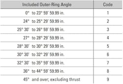
Sections 1 and 2 of this nomenclature are of the most importance when selecting bearings following the ABMA inch-numbering system. Section 1 series prefix consists of one or two letters that designate the duty-class for which the bearing is designed, see Figure 6 (left.) Thin Section L & LL type bearings should be given primary consideration when speed is of concern due to their smaller section and lower heat generation. Section 2 is the angle coding (1 – 9) as determined by the included angle of the outer ring. The smaller the angular designator the higher the K-factor, see Figure 6.
Some ABMA (inch) part numbers are designed with metric envelope dimensions. The J prefix is used in conjunction with the ABMA part-numbering system to identify metric-dimensioned and toleranced inner rings and outer rings.
The J prefix is shown before the ABMA prefix letters. J-Line bearings are referred to as inch bearings with metric bore, O.D., and width. Sections 1-5 are the same as the ABMA inch-part numbering system nomenclature.
A range of metric bearings originally designed by The Timken Company also were included in the ISO 355 plan and are identified with a J-prefix, which indicates a metric dimensioned and toleranced bearing, as shown in Figure 8. Section 1 is the Duty designator, Section 2 the inner ring bore diameter in millimeters, and Section 3 the component designator (cone, cup, flanged cup, etc.)
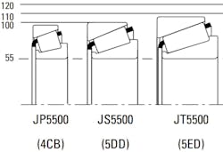
These bearings are specifically application-oriented and are designed for optimal performance, as indicated by the “Duty” designator in Section 1, see Figure 9.
Depending on application and type of load, thrust and/or radial, the bearing with the optimal angle and section can be selected. For example, pinion bearings have a steep angle (metric-duty J-type S&T) whereas bearings for machine tools are generally designed with a shallow angle and a light section (metric-duty J-type P), see Figure 10.
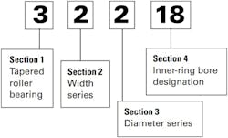
The original metric part-numbering system for tapered roller bearings was based on the ISO “15 dimensional” plan for radial bearings. A five-digit part number commencing with numeral “3” describes the tapered roller bearing assembly (inner rings and outer rings), see Figure 11.
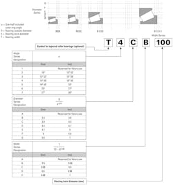
As dimensions given by the ISO 15 general plan were not found to be optimal for tapered roller bearings, ISO introduced a new numbering system for tapered roller bearings in ISO 355, see Figure 12. The numbering system of ISO 355 uses three alphanumeric fields to define a dimension series. The bearing part number is then defined by adding the inner-ring diameter in mm after the dimension series. Although the original metric part numbers were assigned a new designation in the ISO 355 plan, the original part number is still used.
Understanding part numbering systems is important when searching for an optimal TRB for a machine tool application because it defines the best candidate bearings. This is especially beneficial, because availability in the desired precision class may be limited, so having choices increases the probability of locating a bearing that meets both the application and lead time requirements.
This is the first installment of a series, “Selecting, Configuring and Lubricating Tapered Roller Bearings for High-Speed Machine Tool Spindles.”
About the Author
Eric Faust
Application Engineering Specialist
Eric Faust is an Application Engineering Specialist at The Timken Company, providing sales and customer support with technical bearing expertise and helping to resolve customer performance concerns.

