MACHINE FEED DRIVES that use ball screws that incorporate rotary encoders are prone to position measurement error as a result of thermally induced expansion because the ball screw drive serves a double function: On the one hand it must be as rigid as possible to convert the rotary motion of the servomotor to linear feed motion while, conversely, it must serve as a precision measuring standard.
This twofold function forces a compromise because both the rigidity and the thermal expansion depend on the preloading of the drive's ball nut and the fixed bearing, and both the axial rigidity and the moment of friction are roughly proportional to the preloading.
Drive friction
The recirculating balls within the ball nut generate most of the friction within a typical ball screw feed drive system. Besides rolling through their races and the adjoining ball screw threads, the balls are subjected to micro-slip caused by the relative motion in compressed contact areas. Additional friction occurs because the ball races do not completely hold the balls from all sides, causing them to wobble much like tennis balls rolling down a gutter. The wobble produces continual pressing and pushing with occasional slippages. The friction is further aggravated by the absence of a retaining device — in most ball nuts — that can separate the balls and eliminate high surface pressures.
In research performed by engineers at Heidenhain (www.heidenhain.com), measurements of the moment of friction, various preload forces and rotational speeds of a typical ground precision ball screw with a 40 mm (1.575in.) diameter and 10 mm (0.394-in.) pitch confirmed the high share of solid-body friction and mixed friction in ball screw drives at low speeds. Viscous friction dominated at high speeds; however, for the ball screw described, normal machining feed rates were shown to lie far below the speeds at which the moment of friction is at its minimum. The opposite was true at rapid traverse feed rates.
The feed rates at which this ball screw was at optimum efficiency therefore seldom occurred. The moment of friction was only slightly dependent on the axis load of the ball nut.To increase rapid traverse velocity, either the pitch or the rotational speed of the ball screw must increase. In the last 5 years, the maximum permissible speed of such ball screws has doubled; however, due to the continually increasing requirement for acceleration, the preloading and therefore the friction of the ball nut could not be reduced. Ball screw drives, therefore, generate significantly more heat than before and will generate even more in the future.
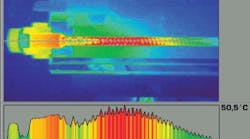
According to Heidenhain research, if a feed drive ball nut has a typical preload of 3 kN (2212.7 ft/lbs.) and a missing wiper, the unit's no-load or frictional moment would be 0.5 to 1 Nm (0.369 ft/lbs. to 0.738 ft/lbs.). In rapid traverse at a ball screw speed of 2000 rpm, approximately 100W to 200W of frictional heat would be generated in the ball nut. Such an amount of heat is enough to cause expansion of the adjoining feed components, and with typical time constants of 1 to 2 hours, the positioning error due to thermal expansion can be in the magnitude of 0.1 mm, depending on the nature of the part program. This positioning error therefore outweighs the thermally induced structural deformation and geometric error of machining centers.
Ball screw bearing design
A suggested rule of thumb for thermal expansion is that, over the entire length of a cold ball screw 1 meter in length, the ball screw grows by approx. 0.5 to 1 µm after every double (back-and-forth) stroke. This expansion accumulates within the time constant. After every new part program, a feed drive system as just described would require approximately 1 hour to attain a thermally stable condition. This also applies for interruptions in machining.
Differing types of heat expansion behavior depends on the types of bearing systems used to support the ball screw. For example, a ball screw using fixed/floating bearings will expand freely away from the fixed bearing in accordance with its temperature profile. The thermal zero point of such a feed axis lies at the location of the fixed bearing. This means that theoretically no thermal shift would be found if the ball nut is located at the fixed bearing. All other positions will be affected by thermal expansion of the ball screw.
The situation is more complex in the case of fixed/fixed bearings. Ideally, rigid bearings would prevent expansion of the ball screw at its end points. However, this would require considerable force. To prevent expansion of a ball screw with 40 mm (1.575-in.) diameter, 2.6 kN (1917.7 ft/lbs.) of force must be applied to the ball screw per degree Celsius of temperature increase.
A typical angular-contact ball bearing would quickly fail under any large increase in temperature. Under real conditions, the rigidity of the purportedly fixed bearings with their seats lies in the area of 800 N/µm (more than 4.5 million pounds of force per inch). This means that as the temperature of the ball screw increases, the bearings deform significantly, and the end points of the ball screw move by 20 to 30 µm (0.000787-in. to 0.0011811-in.) in the direction of the force generated by heat.
This means that by designing fixed bearings at both ends, the expansion could be halved. The thermal zero point of the feed axis seems to lie at the midpoint of the traverse range. This is also expected because the bearings have approximately equal rigidity and the ball screw was heated evenly over its entire length.
A fixed/preloaded bearing design is often used as a sort of pressure valve. With a typical preload of 50 µm/m (.00005-in./in.), one would expect that such a bearing configuration would behave like a fixed/fixed combination up to a temperature increase of approx. 5 deg. K (4543 deg. F), and beyond that, like a fixed/floating combination.
Countermeasures
Many ball screw systems use a rotary encoder attached to the screw's drive. The encoder counts number of rotations, as well as identifies partial turns, for the control computer to convert into position data. However, such an encoder cannot recognize if the overall length of the ball screw has changed. If a feed system is subject to error due to thermal expansion, a linear encoder can be added, or installed as a substitute for the rotary encoder. A linear encoder provides data based on the actual position of the ball nut, and usually incorporates a thermally stable material in its construction.
Another measure to use coolant conducting hollow ball screws. However, the circulation of the coolant requires a hole in the ball screw and, for rotating ball screws, rotating bushings near the screw bearings. Apart from the sealing problems, the hole reduces the ball screw's mechanical rigidity in its already weak axial direction. The greatest problem, however, is a sufficiently accurately temperature control of the coolant.
Research is underway on compensation of thermal deformation within the control software, with the aid of analytic models, neural networks and empirical equations. However, the main focus of these studies is in the deformation of the machine tool structure as a result of internal and external sources of heat. There is little interest in investigation into compensation of axis drift.
Thus, as machine tool accuracy and velocity requirements increase, linear encoders for position measurement should be taken into consideration when deciding on a feedback system design.
Editor's note: this article was derived from a white paper produced by Heidenhain. The full text of the paper can be found at http://www.heidenhain.com/?/c: 2243;177,Documentation+Portal:846/c:2238;177,Services +and+Documentation:2243/c:846;177,Brochures%2FCDROM%2FDVD:813.html under "Length Gauges" and titled "Technical Information - Accuracy of Feed Drives."
