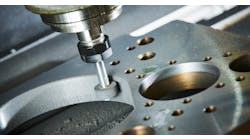
A practical, portable hardware/software system monitors and records creepfeed grinding's "vital signs" to minimize thermal damage.
By David Graham and John A. Webster
Saint Gobain Abrasives
Edited by James Benes
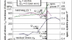
Surface-quality measurements plotted against specific material-removal rate indicate corresponding threshold of burn.
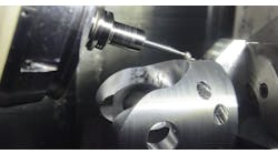
FIS analysis of slotted and unslotted workpieces indicates a high material-removal rate is achieved with an unslotted workpiece and intermediate coolant flowrate of 3.1 l/m/mm.
Plot of ratio of coolant flow vs. hp/unit width shows coolant flow is sufficient to quench grinding energy to reach pass, except the first.
Thermal damage is detrimental to creepfeed grinding operation. But application engineers at the St. Gobain Abrasives' Higgins Grinding Technology-Center (HGTC) offer remedy to the problem using the company's Field Instrumentation System (FIS). FIS shows how the heat generated during grinding affects workpiece and process integrity and points out ways to optimize coolant flowrate, pressure, and nozzle design to produce quality parts.
FIS technology is a portable system of hardware and software that measures and records the variables impacting grinding. The system uses Hall-effect current probes and a linear variabledifferential transducer (LVDT) to measure and monitor power consumption, slide position, cycle time, and product behavior over time. The transducer signals are collected by a data-acquisition system, converted to quantitative process data by the FIS software, and stored on a laptop.
Using FIS, engineers compare several coolant-application models, measuring power forces and displacement, to determine which gives adequate cooling at maximum material-removal rates. In each test they set coolant pressure to match wheel speed and adjust the aperture to obtain the correct flowrates. They also measure ground surfaces using established techniques — visible burn, power surge, Barkhausen noise, hardness, nital etch, and residual stress — to determine when the quality of a surface is damaged by the grinding process.
Engineers then plot surface-quality measurements against specific material-removal rates and the corresponding threshold-for-burn indicated. Residual stress is the earliest indicator of thermal damage as material-removal rate increases and is the most sensitive indicator. Spindle-power increase is the easiest-to-use measurement technique, nondestructive, and detects burn soon after a compressive-stress threshold is reached.
The next step is to use the FIS to plot coolant flowrate versus power at the point of power increase for each wheel speed. This step can show if the amount of coolant reaching the grind zone is constrained by wheel porosity, limiting its ability to carry coolant through the grind zone, or by the amount of applied coolant.
In tests with no precut slots, which constrain coolant from exiting the sides of the wheel, the test grind produces an increase in hydrodynamic pressure. In this case, it's possible to use a lower coolant flowrate and still achieve higher material-removal rates than using a side flow allows.
Reducing grinding burn
An equipment manufacturer wanted to improve final surface creepfeed grinding of cutting blades manufactured of heat-treated 1526 hot-rolled steel. Grinding productivity was limited by heat generated burn. Increasing wheel speed didn't take care of the burn problem, so St. Gobain engineers reviewed the process. They conducted spindlepower measurements and audited the coolant-delivery system to check pump capacity, feed-pipe diameter, nozzle distance to the grinding zone, pressure, and nozzle design.
They took three 0.005-in. d.o.c. and a final 0.003-in.-depth pass, using an electroplated CBN wheel with straight oil coolant. The coolant pump was a 15-hp multistage centrifugal pump with maximum pressure of 280 psi. Operating pressure, measured at the pump, was 120 psi due to large nozzle apertures. A 40-psi extinguisher nozzle quenched sparks from the grind.
Using the FIS unit, engineers recorded power graphs that plotted specific power for each pass for 15 parts. With each pass, the width of contact increased as more of the angle was ground. With the first pass, specific power varied significantly and was higher than with subsequent passes. This was from variation in the previous milling operation and part distortion during heat treatment. As the contact width increased during passes two and three, total power also decreased, resulting in lower specific-grinding power.
For all but the first pass, coolant application sufficiently quenched the grinding energy. However, although the flowrate was adequate, coolant was not reaching the grind zone due to air entrainment caused by poor jet coherence and the air barrier surrounding the wheel, which deflected coolant. As a result, HGTC engineers designed a new coherent jet nozzle to match the higher wheel speed.
With the new nozzle, pressure at the pump increased to 170 psi. Based on field experience, testers estimated a 20% drop in pressure between the pump and nozzle, giving a jet velocity of approximately 9,000 fpm. This amount was sufficient to penetrate the air barrier at the higher wheel speed. Engineers then ground parts at the existing material-removal rate and, with the wheel speed increased 20%, the removal rate increased 20%, with no evidence of part burn.
Thin-part warping
In another example, a manufacturer of electronic-equipment hardware experienced high scrap rates in the production of thin plates due to variation in part thickness. Although the company used creepfeed technology to grind both top and bottom surfaces in two operations, it had difficulty maintaining a tolerance of ±0.0002 in. The problem, believed the firm, was the result of inadequate coolant application during final grinding leading to excess heat and undesirable part stresses. Excess surface stresses can distort thin parts, making it hard to maintain part geometry. Therefore, the manufacturer asked HGTC engineers to analyze the operation, with particular attention paid to coolant application.
After heat treatment, double-disc grinding, and machining of holes, the flat blanks go on to final grinding. The first operation grinds the bottom surface; the second operation finishes the profile on the top of the part.
Both operations take place on three-axis, CNC-controlled grinders with vitrified CBN wheels and employ CNC programs that maintain constant power for all passes based on the ampere load meter on the machine controller. To accomplish this, the d.o.c. and table speed for some passes are different. HGTC engineers used low material-removal rates for the final finish passes of both operations to reduce grinding forces, minimize machine deflections, and improve-part accuracy. They also used water-soluble oil coolant and set the pump-motor speed in the CNC program to control flow and pressure.
As is typical, the power for the passes in the down-grind mode drew less power than passes in the upgrind mode. The second operation consumed approximately 25% more power than the first operation and almost twice the specific power.
HGTC engineers calculated coolant flow versus grinding power for each pass. When only a portion of the wheel width is engaged in the grind, the effective flowrate must be adjusted to compensate for the portion of the stream not passing through the grind zone. Engineers found the second operation had poorer coolant application than the first. This reduced coolant flow caused excessive heat in the grind zone, which, in turn, caused thin parts to warp from unbalanced stresses created in the material.
To avoid these stresses, engineers suggested increasing coolant flowrates by boosting the pressure for both operations, paying particular attention to the first few passes of the second operation. This action, they told the company, would generate a coolant stream closer to the wheel speed to penetrate the air barrier around the wheel. In turn, this would increase the effective coolant reaching the grinding zone. Alternately, the company could add an extra pass to keep the unit power and material-removal rate more consistent. This option is possible because the unit power for the first several passes of the second operation is significantly higher than the rest.
However, HGTC engineers caution that preventing undesirable residual stresses during these two grinding operations may not be sufficient to avoid part warping. Residual stresses from heat treatment, double-disc grinding, drilling, and counterboring may be adding to the difficulties with holding flatness and form tolerances. Stresses induced during earlier operations may be released during grinding with a similar effect on part flatness as stresses induced during grinding.
| Keeping creepfeed grinding cool Excessive heat generated during creepfeed grinding can cause residual stresses and hardness changes to the surface being machined. The depth and magnitude of these stresses are determined in large part by the temperature produced during grinding. Adequate coolant application reduces thermal damage to the material, allows higher wheel speeds, and increases grinding productivity. An easy-to-apply method of estimating the amount of coolant required is to use the model of 2 gallon/min per grinding horsepower. In addition, shops should address factors such as jet coherence and jet velocity adequate to penetrate the air barrier. In production operations, it's also a good idea to examine the geometry of the process to understand the principles of coolant application. For the most part, fluid velocity should match wheel velocity. However, limitations of pumps, plumbing, and nozzle design may not permit this. As grindingwheel velocities increase, a coolant system may be unable to supply optimal jet velocity. Therefore, care must be taken in the design of the nozzles to match flowrate to the power consumed during grinding. The diameter of the hose, or pipe, from the pump to the nozzle affects the pressure drop prior to the nozzle and the length of the pipe and its internal surface roughness also affects pressure. Where possible, straight pipes or hoses of sufficient diameter to support the required flowrate should be used before a nozzle and transitions between pipes and nozzles should be smooth and without a step. |
Mr. Graham is a research engineer and Dr. Webster is a research associate at the Higgins Grinding Technology Center at Saint Gobain Abrasives, Worcester, Mass.
