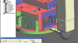
Inspected part showing probe points
Creating a program to have a Coordinate Measuring Machine (CMM) inspect a complex part is a time-consuming activity that can take hours and sometimes days to complete.
However, a new software package has been developed to reduce that time by as much as 90 percent. The package is called PAS CMM, and is being distributed in North America by PAS Technology (www.pastechnology.com).
Developed in Israel, the package has more than 50 customers, including Israel Aerospace Industries Ltd.The software works as a frontend to existing CMM programming software applications.
It uses automatic feature recognition and advanced analysis tools to analyze a CAD part model and to automatically generate code in standard CMM formats such as DMIS, PCDMIS and COSMOS.
The process is similar to using a Computer Aided Machining (CAM) package to create CNC code for machine tools.
“Using PAS CMM, the entire process of creating an inspection program for any CMM machine can be completed in minutes rather than hours or days,” Sam Golan, president of PAS Technology, said. “The CMM program can be simulated and verified in a virtual machine environment, then transferred to the inspection machine in a standard CMM format. In addition to reducing CMM programming time by as much as 90 percent, the PAS CMM program enables companies to develop and easily enforce a set of inspection standards to suit their needs,” Golan said.
The software works in three simple steps that begin after a 3D model is imported to the program in any of the standard file formats such as IGES, STEP, VDA, Parasolid and SAT.
The first step is automatic feature extraction. Normal inspection features such as holes, bosses, rounds, chamfers, surfaces, and planes are identified and stored in a feature tree. This structure of features then is divided into inspection sets that consist of probe orientations, and lists of features that can be inspected in the various orientations. The software allows users to edit and add inspection directions, or to edit features or to move features from one division to another.
The second step is automatic inspection. Measurement locations — probe points — are created for each feature according to its geometric type, the specified inspection mode and the general properties that are set for the process, such as accuracy and tolerances. Tilt and rotation values are calculated for each measurement location according to the defined inspection direction while taking into account the accessibility by testing probe and holder for collision.
The third step allows for quick annotation. Through the use of an annotation tool, the user can specify the inspection requirements and the form of the report required for specific features. The dimension elements created by the user are translated automatically to specific inspection commands, creation of datum elements and specific output commands.
Golan said that PAS CMM provides an efficient and highly automated link between a 3D CAD model and the creation of the inspection DMIS code. The software enables the creation of inspection processes by non-expert users either in the engineering environment or the quality assurance environment. PAS CMM works with all CMM machines.


