Determining the Profile Angle of Hob Teeth for Milling Roughing Straight-Sided Splines
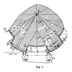
The teeth of a hob form a trapezia with two lines from sides under angle @. See Figure 1, which shows a spline shaft and teeth, pictured together. If we know the angle @ of the teeth we can change an allowance ^ in roughing straight-side splines at the time of milling.
After milling we will have on the sides of the spline allowances like two curves on the sides of the spline with the size of the allowance for grinding operation.
After grinding these allowances we will have the finish size of the spline according to the drawing. The milling can be made on the milling spline cutting machine, and the grinding on the grinding spline machine.
The calculations for these steps are very short and simple:
1. tg@ =MK/h
2. MK = S / 2 - LM, LM = CE,
3. CE = CQ - EQ
4. CQ = (d/2)xtg(p/Z)
5. EQ = (b/2)/cos(p/Z)
6. LM = CE = (d/2)xtg(p/Z) – (b/2)/cos(p/Z)
7. MK = S/2 – (d/2)xtg(p/Z) + (b/2)/cos(p/Z)
8. tg@ = {S-d x tg(p/Z)+b/cos(p/Z}x1/(2xh).
p = 3.141593, ^-allowance
s,d can be calculated easily by a tool designer, from a book of tool designs.
d = dnom +^, b is bnom,
s is the hob thickness on the pitch line.
About the Author
Mark Grizotsky
Owner
Mark Grizotsky, owner of MLG Tool Design in Willowdale, Ontario, has been a major contributor and influencer to machinists everywhere with his insights to machine design and set-up, tooling design and selection, and advice for preparation and processes.

