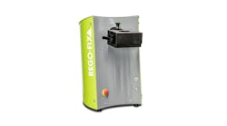
Ballbar testing optimizes manufacturing of high-tolerance parts.
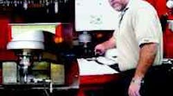
Calibration specialist Richard Grimes keeps Smith & Nephew's CNC machines operating at Six Sigma standards through routine machine calibrations using Renishaw's QC10 ballbar system.
Renishaw's QC10 ballbar measures contouring errors that are only apparent when the machine is in motion, converting data into a polar plot of the machine's true movement.
Renishaw's Windowsbased ballbar software is designed for userfriendly interface and quick setups.Tests typically take 15 min per machine.
In medical, aerospace, and other precision industries, ballbar testing is essential for quality control — determining a machine tool's capabilities before post-process part inspection. The ballbar sees motion-effecting errors that exist in the axes, including backlash, reversal spikes, lateral play, cyclic error, servo mismatch, scaling errors, and geometry errors such as squareness and straightness.
Besides isolating errors, the ballbar facilitates process optimization. As an example, users can determine what feedrate delivers the best accuracy for a specific cutting procedure through dynamic checking of the machine tool as it is driven at different feedrates.
Process optimization was the goal at Smith & Nephew Orthopedics, Memphis, when it reviewed plant effeciency in 1998. As a maker of medical implants, S&N wanted all of its 325 machines tools to produce precision parts to a "Six Sigma" standard. Unfortunately, preliminary diagnostics revealed the machines were running at a Three Sigma level. So Richard Grimes, a calibration specialist in charge of the company's CNC testing, repair, and validation program, implemented ballbar diagnosis on all machines to isolate problems and restore tight tolerances.
When running tests, S&N was on the look out for all the common errors that erode tolerance, including:
- Axis reversal spikes, which appear when an axis being driven in one direction pauses momentarily at the turnaround point instead of reversing smoothly to move in the opposite direction.
- Scale mismatch, which indicates that one machine axis is either overtravelling or under travelling relative to the other.
- Backlash step, indicating lost motion from backlash. An outward step suggests play in the drive system, while an inward step indicates hysteresis in the CNC encoder. Either step could also be caused by play in the machine guideways.
- Stick-slip "noise," which results when friction causes one axis to stick when it is fed at a low rate.
- Squareness error, occurring when normally orthogonal axes are no longer moving at 90° relative to one another.
- Servo mismatch, which indicates mismatched servo gains in the CNC, causing the axis with the higher gain to lead the other and making precise circular interpolation impossible.
- Cyclic error, shown as a plot with waviness that varies in amplitude and reaches maximum amplitude at axis reversal. This error is caused by a flaw in the axis leadscrew or leadscrew mounting.
- Master/slave changeover error, which often results on CNCs that only interpolate one axis at a time. This can vary the speed of the "master" axis while the "slave" axis follows generating arcs.
In all, Grimes uses the ballbar to check 13 performance parameters. The company's quality department determined that those 13 items combined must not be off by more than ±0.003 in. The plant's machine tools are now operating at true Six Sigma, or 0.0003% failure rate.
"We now make better products and have less downtime since we catch problems before they happen," says Grimes. "When new equipment comes in, I first test the machine with the ballbar. If a machine is moved, crashes, or loses a spindle, I run a ballbar test. Regardless, each machine gets an annual test and will not run until it meets or exceeds our established spec."
This regimen of periodic ballbar checkups and recordkeeping allows Grimes to keep his huge army of CNC machines at the Six Sigma level.
Another high-accuracy manufacturer, Hamilton-Sundstrand—maker of aerospace fuelhandling systems,auxiliary power units (APU), and wing flap actuation systems—tests regularly for errors on its machines to ensure that wear and temperature changes don't affect tight tolerances.
The Grand Junction, Colo., plant specializes in the machining of extremely tight-toleranced complex housings, forgings, and hog-outs. Most parts have complex geometries that require 4 and 5-axis CNC equipment to produce typical aerospace tolerances of 0.001-in. true position, ±0.0005 in. diameters, and surface profiles of 0.002 in.
At the first sign of any nonconformance in parts, the machinist sets up and conducts a ballbar diagnostic test. The test checks 14 different geometric parameters in each of the three machine planes—XY, XZ and YZ. Errors are quickly identified, then corrected by maintenance personnel.
Employees also use ballbar tests to regularly monitor the performance of all its CNC machine tools. This reduces unscheduled downtime by tracking trends in machine performance. The company identifies problems before a machine tool goes down, allowing for scheduled repairs, rather than production crises.
The ballbar has also reduced the time needed to complete routine preventive maintenance. Ballbar data lets the maintenance technician determine the true extent of any corrective action a machine may need. In many cases, the machine requires fewer adjustments than normally scheduled.
| Ballbar 101 A ballbar monitors machine tool spindle movement as it follows a programmed circular path and compares it to that of a perfect circle. The ballbar consists of a telescopic bar with precision-machined, magnetic ball-and-cup joints at either end. The bar houses a high-accuracy position sensor. One end of the ballbar typically mounts via a patented magnetic cup to the machine bed, while the ball at the other end attaches to a magnetic cup in the machine's spindle. The ballbar's internal sensor contains two coils and a moving core. As ballbar length changes, the core moves inside the coils and causes a change in coil inductance. Sensor circuitry detects inductance change, which is converted to a position readout with a resolution of 0.1 µ and an accuracy of ±0.5 µ at 68°. A typical ballbar test may sweep a 4-in. radius, but tests in the range of 2 in. to over 40 in. are possible. Different lengths have different sensitivities to particular errors. For example, a longer length increases sensitivity to geometry errors such as squareness, while a small radius highlights dynamic errors such as servo mismatch. A small circle kit enables test radii of as little as 0.590 in. to be carried out. Other accessories available enable the ballbar to be mounted between the spindle and turret on lathes and VTL's. Ballbar tests typically take only 10 to15 min and can be performed in full-circle or any angle X-Y, X-Z, or Y-Z arc traces. After ballbar installation on the machine, the tester programs the machine to drive its spindle in a circular path with a radius equal to the length of the ballbar. The ballbar tracks spindle movement, weighs errors based on the measured values, and converts the ballbar data into an error-exaggerating polar plot of the machine's true movement. An experienced user can identify every error in the machine from this plot; however, sophisticated algorithms in the ballbar software produce a comprehensive diagnostic report that counts up to 22 different dynamic and geometric error values. The software then ranks these errors and calculates the overall positioning capability (true position) of the machine. If needed, shops can test in accordance with ISO, ASME, or JIS standards. |
Clive Warren is the Business Manager, Calibration Products Division for Renishaw Inc., Hoffman Estates, Ill.
