To speak of the aerospace industry is to imply “precision”: One instantly thinks of beautifully engineered airliners, awe-inspiring jet fighters, and rockets to the moon and beyond. Aircrafts are manifestations of imaginative engineering and precise manufacturing execution. In a mere hundred years, airframes have evolved from a few tubes held together by piano wires to complex engineering marvels made of space age materials.
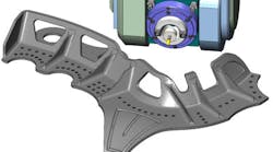
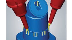
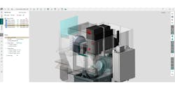
Aerospace component being machined on a virtual 5-axis machine.
The first airplanes started as hand-made contraptions and as flying evolved the tools for manufacturing them also improved. In Seattle, Boeing offers a first-rate museum displaying some of the tools and processes of aircraft manufacturing infancy.
The aerospace industry continues to be the driving force behind developments of cutting-edge technology. Many CAD/CAM, verification, and inspection tools have been developed specifically for aerospace applications. For example, before the development of CAD/CAM systems airplanes were designed on drafting tables, patterns were made, and manufactured parts would be measured with those patterns. Then, as the first NC (numerical controlled) machines were introduced, paper tape code would be typed on a flexowriter and this tape would drive the motions of the tools on an NC machine as it cut the part.
The big advantage of this process was that the finished parts would all be very consistent. The whole manufacturing and inspection process would always be documented in detail to ensure maximum consistency and accuracy. Manufacturers would have to be able to send a replacement part for any airplane, in short order, to any point on the globe and guarantee a perfect fit.
CAD/CAM systems have evolved. Now it is possible to design the part on a computer, generate a G-code program, and then verify it with solid-model material removal. NC machines eventually were replaced with CNC (Computer Numerical Control) machines, which have on-board memory so the paper-tape method obsolete. But, there were thousands of old paper tape programs and approved processes in existence. Those part files remained on paper and the only way to measure them was with the patterns.
This was an interesting problem because the parts could be made from those legacy paper-tape programs, but there was no CAD model available. Some of those old programs only worked on a specific machine. The challenge was to reverse-engineer those parts.
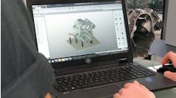
Multiaxis toolpath refinement testing in Mastercam lab.
VERICUT by CGTech came up with an interesting solution:their solid-model verification process would create a solid model of the part as they simulated the old paper-tape code. Then, they would export that model as an IGES model to your CAD/CAM system of choice, enabling you to create modern, more efficient toolpaths for any machine available.
Many of today’s 5-axis machines were designed for aerospace manufacturing applications, and we all like to think that today’s modern 5-axis machines are highly accurate.
CAD/CAM systems allow us to generate toolpaths with unlimited theoretical accuracy. You can generate 5-axis toolpaths with 0.00005-mm cut tolerance, but do you really believe that the actual cut part will also have that accuracy? Where was the CAD model generated? If it was generated outside, how was it translated? With what tolerance value? How many translations were made? And what translation tolerance values were used?
There is a measurable difference between the virtual and the real world. There are a few things that will influence this difference.
No machine is perfect. They all have some acceptable inaccuracy built into them. The three-linear axes are never perfectly perpendicular to each other. The rotary axes are never perfectly aligned to each other, nor to the linear axes. On top of this, all of the machines axes will have some “wobble” – the linear axes are not travelling in a perfectly straight line and the rotaries are not perfectly balanced. The spindle is always running out some amount, and it is never perfectly aligned with the linear axis carrying it. Perfect, of course, is zero tolerance – a perfect machine couldn’t move.
Placing a near perfect machine on a dynamically weak floor would ruin its accuracy and performance. Leveling the machine’s table is a good start, but it is not enough. Bounding a machine to a dynamically stable floor will make it much less prone to vibration.
A super-tuned, but less expensive, machine will perform significantly better than a poorly installed, high-priced machine. IQL Engineering Services provides solutions for enhancing the volumetric positioning performance of CNC machines. IQL SuperTune is an on-site process that combines low-impact anchoring and precision alignment/adjustment, resulting in high machine stability and optimum positioning performance. New and existing machines can be SuperTuned. IQL SuperTuning can be executed in a few days to minimize production impact.
A Flexowriter machine was needed to type paper tape code used to guide the movements of an NC cutting machine.
The machine shop environment is critical. Constant ambient temperature and humidity must be maintained. Inspection always must be performed at a specified temperature.
Machine builders added many features toward maintaining precision. Intelligent controllers are constantly monitoring the loop between command and execution. Some have nano-smoothing options to achieve better synchronization of movements between all axes, linear and rotary. Warm-up routines are used, thermal stability is maintained, and dynamic self-diagnostic routines are performed.
‘Wired-up’ machines have monitoring systems installed. These systems can monitor things like the thermal dynamics of the machine, spindle load, and cutting pressure. Some can adjust tool offsets to compensate for tool wear or even thermal differences during the process. Some systems will alert you if the machines performance signature changes allowing you to perform preventative maintenance instead of catastrophic maintenance.
Routine maintenance of your 5-axis equipment is just as important as keeping your tools sharp and balanced. Using unbalanced tools on a near-precise machine will ruin its accuracy. A dirty machine is an inaccurate machine.
Modern CAD/CAM systems are able to generate precise toolpaths inside their virtual environment. The cutting process is controlled to every minute detail. Many cut patterns can be generated while the tool axis orientation is directed for smooth, refined transitions. Dynamic algorithms ensure collision-free, efficient toolpaths. Then, these toolpaths can be simulated on virtual machines to make sure that no travel limits are violated, that all machine motions are performed as close as possible to the machines “sweet spot,” and that there are no machine component collisions.
The challenge is to synchronize the virtual and the real world. The CAD/CAM systems generic language has to be translated (post processed) precisely to each individual machine’s language, taking into account the performance and capability differences of each individual machine. For a CAD/CAM developer it is not enough to simply keep adding new or cool features. It must be realized that the end product of a CAD/CAM process is G-Code — which will drive the movement of a CNC machine as it cuts the part. This may be the end product of the CAM process but it is only the beginning of the machining process.
As CAD/CAM system development and machine control development work together we can get closer to achieving precision, because each one can complement the other’s strengths and compensate for their weaknesses.
CNC Software Inc.; Mastercam has a 5,000-ft2 applications lab on site, dedicated to connecting the virtual world to the real world. There are multiple machines installed on rotation so that toolpaths, post processors, new strategies, and ideas can be tested and compared. This hands-on lab is used to develop factory approved post processors, tailor-made for each machine.
Precision is a commitment that can make the difference in today’s tough market.
