CNC machine centers offer many benefits over manual machining such as greater productivity, precision production, and reduced labor costs. To upgrade facilities with CNC (computer numeric control) machine capabilities, machine shops can retrofit existing manual machine centers, as long as they are sound and accurate. The retrofit includes converting hand-wheel controls to automated controls with stepper motors. While this sounds simple enough, automating a manual machining center can be very complex, depending on the machine type and layout.
For example, a three-axis manual milling machine might have three control handles or hand-wheels, each moving one of three axes (X, Y and Z). These hand-wheels are connected to some type of screw or other mechanical devices that converts rotation movement to linear movement. Automating the maneuver requires coupling the rotary motion from the stepper motors to the hand-wheel controls.
Machine Torque and Speed
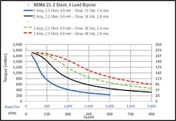
When selecting the right step motors for automating a machine center, you must consider both the torque and required speed. Stepper motors typically have a speed-torque similar to a ski slope. At slow speed, the motor possesses maximum torque. As speed increases, torque drastically drops. Chart 1 supports this fact with a NEMA 23 (National Electrical Manufacturers Association) stepper motor. (See below for more information on motor sizes.) As depicted in the graph, the motor produces 1.70 Nm (240 oz.-in) at 50 RPM but only produces about .045 Nm (63.7 on-in) at 600 RPM with 24 volts DC input to the drive. Increasing input voltage on this motor from 24 to 48 volts, available torque increases from 0.45 Nm at 600 RPM to 0.85 Nm. That’s almost double the torque at the same speed.
Load Determines Necessary Torque
The machine load determines the amount of force need to perform a machine function. A specific amount of torque is needed to generate the force to support the load. As most machining centers use screws to convert rotary motion to linear motion, required torque is the amount of force needed to turn a hand wheel during a machining process.
A simple calculation of load is:
Tf = G x R
Tf = Total force
G = Force
R = Radius
A simple spring scale can measure the required force (G) to turn the wheel at a set point during a machining process. For example, a machining center with a 6-in. diameter hand wheel connected to a screw requiring 12 mm of linear movement for every hand wheel revolution requires 8 lbs. of force to turn it during a machining process at a speed of 8 in. per minute.
The following calculation determines the required torque in the manual process:
R = 6 in./2 = 3 in.
G = 8 lbs..
TF = 8 lbs. x 3 in. = 24 lbs.-in.
To automate this application requires increasing the maximum linear machining speed by 3 times to 24 inches per minute. Increasing the machining speed by this amount also increases the force requirements for this operation by the same amount 24 lbs.-in. X 3 = 72 lbs.-in. (8.14 Nm.)
When replacing the hand wheel with the motor, a timing belt and set of pulleys with 3:1 speed reducing ratio are positioned between the motor and drive screw. The following calculations provide the minimum required torque by the motor at a set speed to meet the desired requirements during machining operations.
Calculations for required torque in automated process:
- TF = 72 lbs.-in/3 pulley ratio = 24 lbs.-in. (2.17 Nm)
- Operation speed = 24 in-min. x 25.4 mm-in. = 609.9 mm-min
- Motor speed = (609.9 mm-min/12 mm-rev) x 3 = 152.5 RPM.
To automate machining operations requires a stepper motor that produces 24 lbs.-in. (2.17 Nm) at 152 RPM.
What is the Required Top Speed?*
The second factor in calculating stepper motor requirements is determining the top speed of a machining center when making a fast move between operations under no load. If an operator can rotate the machine hand wheel at a maximum speed of 100 rpm with no load on the machine and the machine has a linear movement of 12 mm with every full hand wheel rotation, and the required torque to make this move is 16 oz.-in. (0.113 Nm).
The maximum manual linear speed is calculated as 100 RPM x 12 mm per rev. = 1.2m per minute
With the addition of the timing belt and pulleys along with the motor, a 3:1 speed reducing ratio exists between the motor and drive screw. We also desire a maximum linear speed of 2400mm per minute for a fast move.
Motor speed = (2400 mm-min/12 mm per rev.) x 3 = 600 RPM for the motor
16 oz.-in. required torque/3 = 5.3 oz.-in. (0.037 Nm) needed torque at 600 RPM motor speed.
*Please note that all calculations are for general reference and do not factor several unknown variables, such as start-up inertia and acceleration rates.
Choosing the Right Motor Size
Consider the following factors when choosing a motor size for an application:
• Required torque and speed during machining operations
• Required torque and speed during a fast move between operations
• Voltage and power from stepper drives
• Motor physical size
Based on the previous calculations, the torque and speed requirements for the motor include:
• Machining: 2.17 Nm at a speed of 152.5 RPM
• Fast Move: 0.037 Nm at a speed of 600 RPM
To minimize costs, use a 24V power supply and drive that outputs 5 amps.
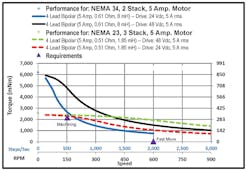
Most motors advertise the holding torque ratio as the main specification. While holding torque is an important factor, it only represents torque produced by a stepper motor to hold the shaft in place at 0 rpm. This specification works for applications that run at very low speeds. However, to truly rate a motor, you need a speed torque chart as shown in Chart 2.
The graphic shows the torque performance of two motors at both 24 and 48 volts input power to the drive. The yellow triangle represents the machining requirement and purple triangle represents the fast move requirement. Both motors meet the requirements for the application and run on a 5-amp drive.
However, the NEMA 23 frame size motor just meet requirements for the machining process but has a holding torque of 3.2 Nm, providing about a 50% torque buffer if the application requires more power.
The NEMA 34 frame size meets the application requirements with torque to spare. It has a holding torque of 7.2 Nm; but, at speeds higher than 600 RPM, it does not perform well.
NEMA 34 motors with the same voltage and current ratings also have two to three times the available torque at low speeds than a NEMA 23 motor with the same voltage and current ratings. (Note: one simple way to increase stepper-motor system performance is increasing the input voltage to the stepper motor drives. Doubling the voltage produces about a 60 to 80% performance increase, if the drives will function at the higher voltage.)
The choice of motor comes down to the machine budget. Typically, a NEMA 34 motor costs about 50 to 150% more than a NEMA 23 motor. If the budget allows for the larger motors, the increased torque may improvement the machining center performance. If the budget is tight, go with the smaller motors that still meet project requirements.
Chuck Leonard is Senior Applications Engineer, Moon’s Industries (America) Inc., a manufacturer of stepper and servo motors, switching power supplies, motor drives, and intelligent lighting control systems. Contact him at [email protected]
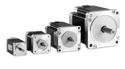
Four Common Frame Sizes for Stepper Motors for Automating Machining Centers
1. NEMA17 (42 mm x 42 mm) are used on the smallest benchtop engraving machines and 3D printers. They have a holding torque range of 0.20 to 0.83 Nm (28 to 120 oz.-in.)
2. NEMA 23 (56 mm x 56 mm) are widely used on small- to medium-sized machining centers and some larger, benchtop systems with moderate load requirements. NEMA 23 motors also serve in laser and plasma cutting systems where the only required force is move the cutting head. Holding torque for these stepper motors is from 0.82 to 3.20 Nm (120 to 450 oz.-in).
3. NEMA 34 (86 mm x 86 mm) are used on medium to large benchtops and free-standing machine centers. They are a good-sized motor for converting all but the largest manual machines to CNC control. Able to produce a good amount of torque over a modest speed range, these motors produce holding torque from 3.70 to 11.90 Nm (520 to 100 oz.-in.)
4. NEMA 42 (110 mm x 110 mm frame) is one of the largest commercially available stepper motors that produce upwards 32 Nm (4532 oz.-in) of holding torque. This motor size is used in industrial machining centers and to convert the largest manual machining centers into high-power automated machines.
These size motors require very-high power drives and power supplies to operate at full potential. Many can be run at higher voltages from 72VDC to 160VDC. A few are rated to run at voltages as high as 360VDC. Increasing input voltage increases the available torque at high speeds, which increases the cutting speed and force of a machining center to shorten machine time for each part.


