The who, what, when, where, why, and how of CMM calibration.
This diagram shows the six possible errors associated with each axis of a CMM. When the three squareness errors are included, 21 possible geometric errors exist.
This diagram illustrates 20 ball bar orientations for a CMM with a nearly cubic work zone. Technicians measure the ball bar's length in each position to determine volumetric performance.
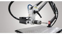
A calibration technician at Brown & Sharpe uses a ball bar along a diagonal within the CMM's envelope to check for volumetric performance.
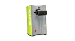
Electronic Measuring Devices uses this Moore step gage to perform CMM calibrations. The gage is quick to set up, is traceable to NIST, and has a total accumulated error of ±8 µin. Standard gage sizes are 12, 18, and 24 in.
Taking multiple measurements of a fixed ball within a CMM's work envelope determines repeatability.
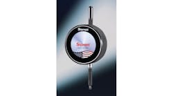
Renishaw's machine checking gage is used for interim checks.
Bal-tec provides ball bars in standard sizes for use in both calibration procedures and interim checks. Using a plastic insulating sleeve during transport prevents thermal heat transfer from the operator's hand to the ball bar.
Many machine shops use coordinate measuring machines (CMMs) to check part accuracy. These shops depend on the CMM's accuracy to verify whether or not part dimensions fall within an acceptable tolerance range. But just like other pieces of equipment, a CMM's accuracy may decline over time. Even the highest quality CMMs are subject to error, but regular calibration can help correct or compensate for this. Although it may be time-consuming and, therefore, costly, calibrating a CMM is better than the possible alternatives — shipping out bad parts good ones. involves adjusting or resetting the CMM so it gives are accurate in comparison to a reference standard, most often from a master set of gage blocks or artifacts traceable to the National Institute of Standards and Technology (NIST). By checking for possible machine errors, calibration determines if the CMM has remained dimensionally stable and nominally accurate.
There are a host of errors that can crop up in CMMs. To start with, 21 possible geometric errors exist, including linear accuracy in the X, Y, and Z axes; squareness of the axes to each other; straightness in the horizontal and vertical direction in each axis; as well as pitch, roll, and yaw in all three axes.
In addition, a CMM's performance is also affected by its own mass, material composition, age, rate of acceleration, vibration (from both internal and external sources), probing system, controller, and environment.
Fortunately, today's CMM software packages can compensate for many errors using input gathered from regular calibration procedures. Operators enter information into the software about each error, basically how much each one deviates from the standard, and the software adjusts its readings accordingly.
Calibration cycle
Most CMM manufacturers recommend an annual calibration cycle. But Mike Napholz, systems engineer at Electronic Measuring Devices Inc., Budd Lake, N.J., points out that users must first identify several factors before they can truly determine an adequate calibration schedule. "Some machines have stricter accuracy requirements, which indicate a need for more frequent calibration, as does a harsh operating environment," he says.
Because a CMM is constructed out of several different materials, temperature swings, both in and around the machine, can cause each component to expand and contract differently. Frequent, large temperature changes may indicate a need for additional calibrations.
Napholz also notes that for CMMs with air bearings, air supply is another factor that contributes to how often a shop calibrates. "Avoid turning air pressure on and off because air regulators do not always return to the same setting. Air bearings have a sixty to eighty-millionths air gap, so one or two PSI can make a difference. Low air pressure prevents machine axes from floating correctly and creates a strain on the drive system. This, in turn, can burn out the motors and score the air bearings, which would then require replacement."
Garth Taggart, president of CMM Technology Inc., San Clemete, Calif., reports that, besides a CMM's construction and environment, real-world experience and cost justification also help determine a calibration cycle. "Some tests are done when a CMM is installed and on certain high-end machines," says Taggart. "But many tests just aren't cost-efficient to perform over and over. However, repeatability, linear accuracy, and volumetric performance tests should be run on an annual basis."
He believes that most small to mid-sized manual CMMs need just linear accuracy, repeatability, and squareness tests, all of which take about one day. But volumetric tests require two to three days, and tests on high-end, CNC-type CMMs, as well as large CMMs, can take up to four days. This is where shops run into cost-justification issues.
As for calibration of new and old machines, the experts disagree. For machines that are older than five years, Taggart advises calibrating twice a year because, in his experience, these machines just don't hold calibrations as long as newer models, which only need annual calibration.
Napholz, on the other hand, reports that older machines tend to have more reliable behavior patterns because, prior to the widespread use of software error compensation, mechanical accuracies were built into the machine. Therefore, technicians can determine an appropriate time schedule for calibration based on those patterns. In the case of a new machine, Napholz recommends calibrating the CMM every six months for the first year or two to ensure that the machine's characteristics and patterns are detected and accounted for correctly.
Calibration specialists
Who calibrates a CMM is left to the discretion of the owner. Some use their respective CMM manufacturer's service engineers, while others opt for the services of an independent laboratory. It is not uncommon for some machine shops as well as research and high-security governmental facilities to train their own employees to conduct calibration tests. The decision is mainly influenced by each shop's level of technical know-how, its relationship with its CMM supplier, company resources, and industry politics.
Napholz recommends that shops use the services of the CMM manufacturer, or if the CMM was upgraded, the manufacturer responsible for the operating system currently installed. As he says, "No out-side source knows the machine as well as the manufacturer does. There is a lot of tweaking that the independent lab technician may not know about."
But machine shops may choose the services of an independent calibration lab based on cost or availability. (From time to time, CMM manufacturers that are maxed out may even take advantage of the available resources of independent labs for contract work.) In some cases, using an outside source can also placate any customer concerns (both the shop's and the shop's customers) about validity. Whatever the reason, managers should look for a few specifics to ensure they receive quality service.
As a security measure, CMM owners considering an outside calibration lab might want to check that the potential service provider is accredited to ISO Guide 25, with particular credentials for CMM calibration. According to Guide 25 requirements, labs must guarantee freedom from commercial and financial pressures that might adversely affect the quality of their work and participate in interlaboratory comparison and proficiency testing programs when appropriate.
Additionally, calibration technicians, whether they be manufacturer's service engineers or independent engineers, should provide some type of paperwork as proof of the calibration results (i.e. test certificate, calibration certificate, or test report). Most manufacturers and independents make up their own form; there is no standard. But various quality specifications spell out what should be on those forms, such as the location where the procedure took place, readings before and after calibration, the tests performed, the instruments used to perform those tests, and so forth. Aside from using an outside source for regular calibrations, one independent lab also suggests that a machine shop has an independent technician come to its plant right after a CMM is installed. This way, the shop has an added guarantee that the machine is performing up to par before finalizing the purchase with the manufacturer.
Calibration standards and procedures
Not all calibration technicians perform the exact same measurement tests. This is due, in part, to the fact that the standards for CMM calibration are not alike across the board. Plus, the degree of accuracy required and the parts to be measured also dictate what tests are necessary, so manufacturers and independent labs perform different tests with various artifacts and instruments.
As for the standards, there are three primary standards used to verify measuring machine performance: ASME B89.4.1, VDI/VDE 2617, and ISO 10360. They all evaluate overall machine performance but differ in approach — mainly in the number of tests involved and the way in which performance specifications are written. The most involved and lengthy standard is the ASME B89 standard, Methods for Performance Evaluation of Coordinate Measuring Machines, which outlines five basic measurement procedures for assessing CMM performance.
In the first procedure, technicians record multiple measurements of a fixed ball mounted to the CMM's table. The range, or largest measurement minus the smallest one, indicates the machine's repeatability.
To determine linear accuracy, the second procedure involves the use of a step gage or a laser interferometer in all three axes (X, Y, and Z). For illustrative purposes, assume a technician is measuring a 10-in. gage with the CMM in the X axis. The machine reads 9.999 in., so the technician knows that for every 10-in. measurement, there is a 0.0010-in. inaccuracy. He often can enter this information into the CMM's compensation software.
When he repeats the test in the X axis, the CMM will report a measurement of 10 in.
The third procedure calls for measurements of a ball bar. This precision gage has two balls of the same diameter connected by a rigid bar. Ball bars come in various lengths for different sized machines, but for each CMM, operators should use a single ball bar that is approximately 100 mm shorter than the smallest dimension of the work zone. This way, technicians can place the ball bar in multiple positions and orientations within the machine's working volume, while allowing adequate probing access to both balls.
Ball bar test results indicate the CMM's volumetric performance, with the range of readings providing information on the best and worst-case errors. Temperature differences between the ball bar and the CMM are the most common cause of faulty readings. Therefore, service engineers should always let ball bars reach room temperature, or that of the CMM's, before conducting any performance evaluations.
Ball bars are also a part of the fourth procedure. They are measured in four diagonal positions within the CMM's work zone. In each position, the ball bar is checked with two right angle probe offsets, and the difference of measured lengths is determined. Differences are then compared with an offset probe performance specification. This procedure detects Z-axis probe offset errors, which can be important to CMM owners who use articulating probe heads at right angles to the machine's Z axis.
The fifth procedure requires measuring the length of a short gage block in four orientations. These measurements are then compared to a bi-directional accuracy measuring specification. The procedure also checks the validity of the probe-tip qualification.
Not all calibrations follow these exact five procedures. In the case of CMM Technology Inc., each CMM calibration starts with inspecting and cleaning the X, Y, and Z scales. The service engineer then checks all reader heads with an oscilloscope and adjusts them to the proper output. Next, he double-checks the fine adjustment mechanisms in the X, Y, and Z axes for wear and tightens them if necessary. Then beam parallelism is checked and adjusted to the CMM's working surface. The next steps are inspection and adjustment of
perpendicularity or squareness in the XY, ZX, and ZY planes; inspection and adjustment of linearity in the X, Y, and Z axes; and finally repeatability in the X, Y, and Z axes with the client's electronic touch probe. After this combination of re-pair, adjustment, and calibration, CMM Technology issues a calibration certificate accredited to ISO 10012-1 and ANSI Z540, declaring that all calibration readings are documented and backed by a NIST traceability number.
Some manufacturers or labs use a choice artifact when calibrating a CMM. For example, Electronic Measuring Devices uses a Moore step gage, a precision gage from Moore Tool Co., Bridgeport, Conn., to map out errors. Electronic Measuring Devices checks for linear accuracy, straightness, and squareness.
"Usually straightness, pitch, and roll are the main characteristics of the machine," says Napholz. "These aren't likely to change if the machine is constructed from granite. But during the course of a year, the linear accuracy and the squareness of the axes will go out. We use the Moore step gage to assess the extent of the errors and adjust the compensation value in the software until the machine repeatability reads accurately."
Interim checks
Tom Charlton, director of R&D for measurement systems at Brown & Sharpe, North Kingstown, R.I., reports that interim checks are currently popular and are now written into a number of standards. These checks, performed between calibration intervals, are abbreviated tests and don't usually qualify as calibrations. But they do track information that can indicate approaching problems. The key to interim tests is to check something that is likely to change.
"Ultimately," says Charlton, "interim tests act as confidence builders by ensuring that the calibration performed six or nine months ago is still valid. Things happen to invalidate calibrations such as crashes or mechanical and electronic failures. So, suddenly, the last calibration is no longer valid. Interim tests inform you as quickly as possible and at the lowest possible cost."
CMM users may perform different interim tests, depending on their needs. This explains why a number of instruments are available on the market. For example, qualifying the probe tip is one quick test that can be performed on a daily basis, especially by those shops concerned about recent probe crashes. To do this, operators place a precision sphere on the CMM table and touch the probe to the sphere. The CMM subtracts out the radius to determine the center of the probe. If it cannot correctly establish the center of the probe, the machine won't be able to accurately measure parts.
Another interim check is a limited ball bar test, which Eugene Gleason from Bal-tec Micro Surface Engineering Inc., Los Angeles, strongly recommends. This effective interim check involves measurements of a ball bar in as few as four orthogonal positions. Gleason encourages CMM users to perform this quick, seven-minute evaluation of their CMMs every morning or at least once a week. When this check reveals an error, the same ball bar can then be used to systematically trace down the source.
Renishaw Inc., Schaumburg, Ill., has a machine checking gage for interim checks. Operators can use the gage daily, weekly, or monthly -- depending on their needs -- to determine if a CMM's performance has remained stable or degraded.
In addition to interim checks, cleaning a CMM is the best way to extend calibration validity. Napholz recommends wiping down the machine with alcohol and cleaning the guideways every day. "Some CMMs have bellows to protect the ways," he says, "but bellows can hide contaminants and make it harder to clean the machine." Whether a CMM has bellows or not, operators should follow a regular schedule for machine cleaning and inspection.
Volumetric laser calibration and compensation
Optodyne's SD-500 vector measurement system records errors along four diagonals within a CMM's work envelope.
The API 6D laser measuring system uses two differential levels. One mounts on the probe, while the other mounts on the machine table.
Lasers can also be used to perform calibrations. According to manufacturers of laser measuring systems, using a 6D laser system to error-map CMMs is faster and more accurate than traditional methods, which require separate setups with individual sets of optics. Automated Precision Inc. (API), based in Gaithersburg, Md., makes a 6D laser system that simultaneously maps linear displacement, straightness, pitch, yaw, and roll positioning errors.
API reports that its 6D HP laser system is portable, easy to set up, and can accomplish all measurements in three hours. Using generated error maps, the system modifies scale-feedback instructions to the CMM's controller, thus compensating for volumetric errors. The system's design isolates the laser beam delivery from internal sources of heat, letting it record linear measurements with a precision of 0.2 parts per million.
Optodyne Inc., located in Compton, Calif., is another manufacturer offering laser-based systems. Working jointly, the MCV-500 laser calibration system and the SD-500 vector measurement system let operators perform volumetric calibration and compensation. With these instruments, operators collect data for three linear, three squareness, and six straightness errors.