Increasingly stringent safety regulations (for example, the emerging IEC 61508 standard) are driving expansion in the market for machine safety products and technologies. As demand increases for safety in plant and process automation, manufacturers find they must fulfill many requirements before they may supply components that conform to “safety integrity level” (SIL) standards. For development projects according to the IEC 61508, DIN EN 62061, and DIN IEC 61511 standards, engineers and decision makers face the problem of risk assessment, cost, and the influence on their organization.
IEC 61508 details the methods and requirements for minimizing the health and environmental risks for facilities and machines. Anyone who participates in the product lifecycle in any way is affected and responsible. Anyone who wants to sell a SIL product for the first time has to develop the product conforming to the Functional Safety standard. Additionally, a Functional Safety Management program must be established and demonstrated in the organization, in order to apply the shifting of the burden of proof in court in case of an accident.
There are many pitfalls and open questions regarding a company’s processes and product development. Among the details that must be analyzed are a company’s processes, development processes, quality processes, and the skills and responsibilities of its personnel. After the development phase, requirements with regard to fabrication, installation, maintenance, modification, and repair, as well as decommissioning have to be fulfilled.
A sample project in 6 steps
Possible steps for development of a component with Functional Safety:
Step 1a — Safety workshop (technical)
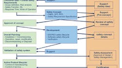
Step 1b — Functional Safety basics seminar (management should be involved) (see Fig. 1)
Step 1c — Safety requirements, Safety plan, V&V plan
Step 2 — Concept approval
Steps 3-5 — Safety hardware and software development (design, integration, test) (see Fig. 2)
Step 6 — Certification
Step 1a: Safety workshop — In a Safety workshop high-level requirements of product management are collected and a preliminary architecture in the form of a system FMEA is created. The safety function and the safe status of the product are characterized.
In more complex projects, it is advisable to involve an independent safety assessor for a pre-concept meeting (an assessor from TUV, IFA, etc.) in order to achieve the concept approval efficiently. (An external assessor can assist during the whole development phase with set-up and evaluation of the required processes. This person should be in a different department, better employed in another organization.)
Step 1b: Basics for the management — Many organizations suffer from tunnel vision. The product manager just looks at his product, the developers just look at their assigned tasks and the management is not aware of the implications of Functional Safety on the whole organization with its processes and activities.
A basic training offered by TUV may be helpful. The topic Functional Safety is explained for all levels of audience related to the future product. Processes are documented as possible consequences.
Step 1c: Safety plan, Safety requirements / concept — The Safety plan shows basis on which the product will be safe; processes and responsibilities are characterized as well as organizational issues. It is the most important document guiding the entire product development.
The Verification & Validation Plan (V&V Plan) shows how, when, by whom, and what will be verified and validated.
In each phase of the lifetime cycle responsibilities, quality management, configuration management, change management, tooling, and methods for error prevention are documented.
Safety requirements and Safety integrity requirements have to be recorded systematically (in medium and large projects a database-based tool will be necessary.) The documents are submitted to the concept review after internal reviews about completeness, testability, and understandability.
Step 2: Concept review — The independent safety assessor reviews the Safety plan, the Safety requirements, and the V&V Plan. Topics may include the safety policy of the organization; organization structure; personnel, responsibilities, and qualification; process description; and standards and guidelines.
The result is a review report with a corresponding list of findings that must be corrected according to the change process. The management board, sales department, development department, etc., may be affected. Afterward, the realization may begin according to the V-model.
At the same time, the assessment process with all planned reviews and reports starts. During all development phases the “four eyes” principle must be applied (planned, recorded reviews with approval by notified bodies.) For this purpose, an author is not allowed to test his own work. Properties and changes must be traceable, in the simplest case with a traceability matrix.
Step 3: Design — For firmware design, the use of a CASE-tool with connection to a requirements database is recommended. Therefore, further errors can be avoided and traceability is easily achieved. The requirements build the foundation for the architecture, upon which the design is created. The finished firmware design is subjected to a software criticality analysis (FMECA or SWCA), where operations are classified with regard to their influence on safety-critical functionality. Control flow and data flow are analyzed for each operation. The outcome will be further methods for error prevention or error control, which must be added to the requirements and realized in the design. Tools for calculations and simulations are used for the hardware design, too.
After creating the hardware schematics, an FMEDA on component level is prepared in order to determine the obtained PFH for each safety function and SFF for the design. Additional measures to be implemented may be an outcome here, too. Then, the design has been finished.
Test cases are specified with regard to the corresponding requirements, i.e., each test case shows which requirements are tested. Often, “black box” tests are defined first in order to guarantee product functionality. Some requirements will remain that need further test cases.
In the end a design review is held by a qualified person in order to verify the fulfillment of all requirements.
Step 4: Design integration — The layout is created (pay attention on clearance and creepage distances), and boards are equipped and put into operation.
The firmware is implemented according to the firmware design documentation. Static code analyses with software metrics, unit tests, and code coverage tests are necessary for quality control. The technique of defensive programming should be applied. A coding standard like MISRA-C may be helpful for error prevention.
As soon as the hardware is developed, it will be put into operation with a test firmware in order to test all interfaces. The integration is concluded as soon as the hardware is confirmed as operable. Then, the main firmware will be integrated in steps with the new hardware.
Step 5: Verification — Black-box tests must be executed in all system levels that have an effect on external interfaces. This includes functional tests under normal conditions, temperature tests, EMC tests, and environmental tests according to the applicable standards. White-box tests in the field of hardware mean characterizing a sample (signal level, signal shape, power, heat) or verifying firmware (timings, interrupts, CPU performance, functionality.) Fault insertion tests in hardware and software are applied to prove that errors are controlled as specified or lead to a safe state. The tests are documented in separate reports (and not as part of the test specification), in order to support repeatable tests by different test teams in the future. Therefore, automated tests should be preferred in any case. All reports have to be saved. Defects have to be evaluated and eliminated according to the defined change process. As soon as the product works within specification, the product can be submitted for certification.
Step 6: Certification — During the certification process the entire development documentation is assessed against all applicable requirements of the IEC 61508. The assessor audits conformity in random inspections of review reports, single component level (hardware), code traces (software), etc. The production site is visited, too. The certificate is obtained as soon as all issues are closed.
In a product development phase the first steps are essential: MESCO supports customers beginning with the IEC standard via the safety concept and its implementation to a producible product. MESCO’s “TUV-certified Functional Safety Engineers“ implement clients' ideas into the required hardware and firmware. Because MESCO provides the customers with all project documentation, product maintenance and further development can remain in the manufacturer’s organization. Customers will benefit from our cooperation with TUV (Fig. 1), from shared and aligned processes, and from the SIL certificate for their product.
Dipl.-Ing. Andreas Keller is a TUV-certified “Functional Safety Engineer” and head of the Functional Safety technology group at MESCO Engineering GmbH, Lörrach, Germany. He also acts as a project manager for safety critical development projects. Contact him at [email protected]
