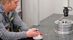
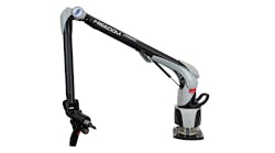
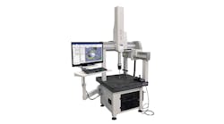
Because of its many advantages, five-axis machining is becoming increasingly common across a range of machining applications.
However, to be able to machine workpieces with the accuracy required for precision parts, the real position of a rotary axis with respect to the machine’s other axes must be known accurately.
The usual methods to determine 5-axis deviations require a considerable measurement effort. However, a measurement system has been developed at IBS Precision Engineering () that the company said accurately determines the location of a rotary axis: The “R-test,” which uses a measuring head in combination with a precision ball.
The goal of the R-test is to measure the rotary axis position in the machine’s X-, Y- and Z- coordinate system. The measured deviations reflect the location errors of the rotary axes directly. These location errors can easily be compensated as the measured values are presented in the machine coordinate system.
How it works
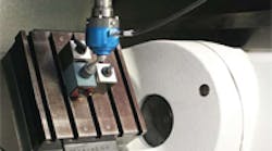
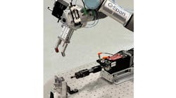
During the R-test, the measuring head, or MT-Check probe, is fixed to the spindle or non-rotating part of the machine. The spindle location with probe does not rotate during the test.
The probe contains three planar elements that are brought into contact with a 22-mm diameter master ball that is mounted on a rotary table affixed to the machine’s trunnion.
Three accurate measuring systems within the probe monitor the displacements of three corresponding contacting elements during this motion. In this way, the center point coordinates of the ball are determined with sub-micron accuracy in X-, Y- and Z-directions.
The R-test can be performed to determine axis deviations during movement of the rotary table or the trunnion table only, or during the simultaneous movement of both.
As the rotary table and trunnion go through their motions, the probe measures the real position of the master ball centerpoint. Readings from the probe are displayed on a laptop near the machine. With the R-test a full, three-dimensional measurement is performed. With one measurement, that usually takes less than two minutes, the location is determined in two directions as is the parallelism of the rotary axis in two directions.
The usual way to measure the center point of rotation of a rotary table is with a dial gauge. By measuring the center hole of the rotary table, its location can be dialed in. However, the problem with this method is that it includes the center hole, so it can never be very precise. Also, the method measures only in one dimension, and has to be repeated to measure in the other direction. That consumes a lot of time.
A standard measurement procedure can be used to determine the center location with a telescopic ballbar measurement. That procedure provides the location of a rotary table, but as with the dialgauge technique, it is a one-dimensional measurement, so multiple measurements are needed to determine axes locations.
The R-test is quicker and more accurate than the more common technique and comes with a full analysis that gives the operator the error parameters in the machine’s coordinate system. Mistakes are not likely because the measured deviations can be used directly in the controller to compensate.
The existing methods of error determination are very complex for trunnion tables.
It is almost impossible to perform a good measurement on trunnion tables with dial gauges, so a workpiece often is made then measured afterward on a coordinate measuring machine. That is a very exhaustive procedure, and interpretation of the measurement result is far from easy and intuitive.
In addition, the R-test also can be used to optimize controller settings. That can be done for linear axes, and for combinations with rotary axes — a difficult task for a controller, especially when heavy workpieces are tilted.
Purpose of the test
The R-test has two primary purposes: As a method of determining axis location errors and as a test for machine acceptance.
Machine builders use the test to determine the center point of rotation and the parallelism of a rotary axis with respect to the machine’s other axes. The center-point location error can be compensated easily in the machine’s controller; the parallelism deviation is more complicated. That alignment error can be compensated in an additional rotary axis, but the compensation usually is done by manual adjustment of the table.
Determination of axis location error also is important to machine tool users, because such errors can be reduced by compensation and/or adjustment to improve machine accuracy.
The R-test also often is used as a total acceptance test — the second major purpose of the system.
When the Masterball is placed in an eccentric location on a table and the machine is programmed to move all available axes, the measured result records all of the machine’s error parameters. Those include geometric errors, such as position, alignment and squareness errors of the linear axes, and dynamic, controller errors, such as following or reversal errors.
Editor’s note: Information for this article was provided by Dr. H.A.M. Spaan, managing director of IBS Precision Engineering (www.ibspe.com) of Eindoven, The Netherlands. The R-test is available from Lion Presicision.
