Rotary tables serve up both speed and torque for multitasking machining centers.

Complex aircraft parts accelerate the market for high-speed, high-torque rotary tables.


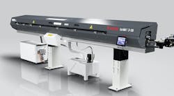
LMC's EDC 400 direct-drive and MDVVi 346 dual-drive rotary tables provide both speed and torque. Current machine tool companies that supply LMC rotary tables include Makino, OKK, Hitachi Seiki, Mori Seiki, Mitsui Seiki, and Ingersoll.

LMC incorporates special split worm gears into its rotary tables to lower gear ratios while still maintaining high torque.
A rotary table's speed and torque always shared a give-and-take relationship. Tables running high rpm generally sacrificed torque, while those that supplied plenty of torque operated at slow speeds. But recent developments now let rotary tables deliver both higher speed and torque without compromising one for the other. As a result, they handle more complex parts and, most importantly, transform machining centers into multitasking systems that turn, grind, and do simultaneous 5-axis machining.
These capabilities let industries such as aerospace and automotive replace multipart assemblies with more complex parts requiring many operations. "As workpiece shapes get more complex," comments Sam Noguchi, product manager at Logansport Matsumoto Co. (LMC), Logansport, Ind., "the market for high-speed, high-torque rotary tables accelerates."
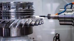
The new generation of rotary tables allows shops to tackle jobs like jet-engine blisks machined from solid disks. There is a lot of material to remove, so machining time for one 5-in. blisk, says Noguchi, is 5 to 7 hours using a standard rotary table. With a high-speed high-torque table, that time drops to 3 or 4 hours.
"And with the speed and torque of these tables," says Noguchi, "shops are running parts on them that they didn't before." Such parts include scrolls for compressors.
Scrolling on a machining center is coordinating X and Y-axis movement to create a round, spring-like pattern. But the scroll is as round as can be done using two axes. No matter how many data points are used, the part is still not a perfect circle, says Noguchi. He adds that because a rotary table is a single rotary axis, it produces a perfect circle and yields a better surface finish. Surface finish is important on scrolls because it affects the air movement through them.
LMC, a rotary table manufacturer, grinds one of its own parts on a horizontal machining center equipped with a rotary table and high-speed spindle. Company machinists hold parts in a chuck, tilt the table, and index to grind slots 120° apart on a 12.5° angle. Normally, the operation is done on a vertical machine and manually indexed.
Two of the company's tables that provide both speed and power are the MDVVi 346 and the EDC 400. The first is a dual-drive geared unit, and the other is a direct-drive system. Both tables provide high speed, 180 to 200 rpm, and high torque — 368 ft-lb for the MDVVi 346 and 511 ft-lb for the EDC 400.
Typically, a single-motor rotary table delivers 30 rpm, but its torque rating suffers because gear ratios are down around 1:60. The MDVVi, however, incorporates a special split worm gear that accommodates a second motor shaft situated 180° from the original shaft. Two separate synchronized motors power the shafts, and the setup lets LMC drop gear ratios from 1:60 to 1:12 while still maintaining strong torque. According to Jay Duerr, sales manager at LMC, it's like a 200-rpm table with the torque of a 16-rpm standard table.
LMC rotates the two halves of the split worm gears to negate backlash with the matching table. The company adjusts the gear phases so that the distance between the gear teeth is shortened. One side of each worm-gear tooth within the length of the action always makes contact with the table gear, while the other side has clearance.
LMC also takes a different approach when it comes to positioning accuracy. "Most rotary tables rely on motor-gear feedback — a motor with an encoder on the end of it," says Duerr. LMC's dual-drive table, on the other hand, integrates a glass scale that sends feedback to the host-machine's control for positioning accuracy within 20 arc sec.
Most often, LMC dual-drive tables are incorporated at the time a machine is built. But they are retrofittable to existing machines by simply adding axes to the machine's control.
Instead of using a worm gear, LMC's EDC 400 direct-drive table has its motor built into the base casting. The casting is actually a huge electric motor with a stator and rotor. This design, which eliminates the use of gears, is a closed-loop system with feedback scales that ensure accurate table movement to within 5 arc sec and repeatability of ±2 arc sec.
Direct-drive tables reach a maximum speed of 180 rpm, but are capable of 200 rpm, and their torque ratings are higher than those of gear-driven tables. Duerr points out that these tables should be integrated while a machine is being built.
Cost is often a deciding factor when it comes to choosing between a gear-driven or direct-drive table, reports Duerr. "Our direct and dual-drive tables are limited to a specific market and cost," he says. A shop with a Makino horizontal machining center equipped with an LMC d u a l -d r i v e table, for instance, is not an average jobshop. Most LMC customers are high-volume producers of complex parts.
Testing tablesRotary-table accuracy, or indexing (accumulated) accuracy, refers to the total deviation of a table's actual position versus a programmed position through a full 360° rotation. Using an autocollimator, LMC inspects all its rotary tables to verify performance accuracy. Technicians index a table in 30° increments in one direction, then measure and note the actual position. They plot this data, and the result is a sine-curve graph. The maximum difference in readings peak-to-peak is the table's indexing accuracy. The test is done two times in the same direction, and the entire procedure is again performed rotating the table in the opposite direction. Each set of data from a given revolution must meet indexing specifications. For most LMC tables that is 12 arc sec total peak-to-peak. The total deviation of all the data collected in all of the tests at any given indexing position, in both directions, indicates the table's repeatability. LMC's final evaluation determines table rigidity and backlash. Inspection personnel rigidly mount a bar to the table face so that it extends 100 mm beyond the table O.D. They then apply a 50-lb force to the bar in one direction and affix a dial indicator on the bar at the table's O.D. Again, they subject the bar to the same force but in the opposite direction. Once the force is removed, the dial indicator must not deviate from its original reading by more than 0.0003 in. for a 320-mm table. Other LMC tables must meet comparable specifications. |