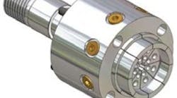
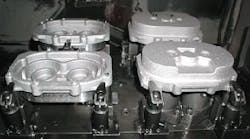
The multiple gripping locations of the ShapeCompliant Hydraulic Chuck from Hardinge Inc. grip a part as-is without forcing an outof-round part to round-up.
Workpiece clamping with electro-permanent square pole chucks and the use of pole extensions from the bottom or side allows for multiple operations in one setup. Illustration courtesy of Schunk Inc.
Delicate or thin-walled parts can be distorted when clamped by conventional workholding devices. Usual clamping techniques also can pose problems for parts that are deformed in their free state, but must be machined true. such parts can be securely held by alternative, innovative clamping and magnetic workholding techniques that do not squeeze and deform a part while conforming to the part's free state.
Clamping Techniques
Consider the problem of holding delicate or thin-walled parts that must be machined true, such as bearing races that are distorted during heat treating. such parts are out-of-round in their free-state and round up when they are gripped by conventional jaw chucks, step chucks or diaphragm chucks. Those parts typically spring back to their out-of-round freestate when they are released.
A solution is to use chucks that include multiple gripping locations, with each gripping location having an independent travel distance to grip the part as-is without forcing it to round up. Parts are automatically centered and can be machined true. That eliminates the need for finish grinding. The technique is applicable for both inside-diameter and outside-diameter gripping applications.
In one application, bearing races were out-of-round before machining by 0.0011-in. on the inside diameter and 0.0013-in. on the outside diameter. Machining with a shape-compliant chuck reduced out-of-roundness to 0.000084in. On the inside diameter and 0.00007in. on the outside diameter, with an inside diameter-to-outside diameter concentricity of less than 0.00004 in.
The use of a force-limiting step chuck is another approach to eliminate the possibility of distorting or crushing delicate or thin-walled parts with a standard power chuck. a forcelimiting step chuck incorporates a spring-loaded design as the primary closing mechanism. The closing mechanism does not depend on the machine drawbar to provide the force with which it grips the part. that eliminates the need to manually tweak the draw-bar force to adjust the grip. the chuck maintains outside diameter-to-inside diameter concentricity, and allows a straight, non-distorted face cut on such features as a thin-wall on an aluminum part. It also allows accurate bore tapers to be achieved.
Another approach to securing round workpieces during machining uses jaws that have teeth that interlock with defined indentations stamped in the workpiece. this type of design between the part and the workholding jaws, eliminates the need for chuck jaws that bite into the raw material under pressure. Stamping the indentations into the workpiece can be done on the clamping chuck or at a separate stamping station. Workpieces held by such positive interlocking with clamping jaws need only a fraction of the clamping pressure that is normally required by conventional forced grip jaws. as a result, workpieces are subjected to minimal distortion, and can be machined with an almost free-from-deformation roundness in the turned diameter. In addition, the tooth form of the jaws has a depth register that allows a workpiece to be removed from the chuck and reinserted into the jaws with a repeatable accuracy of ±0.0002 in.
Savings in raw-material cost is another benefit of this system because the required clamping depth is 0.12 in. to 0.20 in. compared with as much as 1 in. that is typically required with the use of conventional, hard gripping jaws. All materials with a consistency of up to 90 tons per sq.in. (1,400 n per mmµ) can be stamped.
Expanding collets and between-center arbors (mandrels) that grip the internal diameter of a part can be used when the outside diameter of the part is either hard to grip or cannot be gripped. Internal gripping with expanding collets can be used for turning, milling, grinding and assembly operations and for inspection and automation applications.
For part length control and consistency during chucking, parts can be located against the face of the arbor or against a machinable workstop while the expanding collet draws the part firmly against the stop. This workholding technique can add stability for machining long parts. The use of a workstop allows heavy cuts to be made, and provides good surface finishes and close tolerances. Because the part is pulled against the workstop, short grip lengths are firmly held. However, workstops may not be necessary when machining only the outside diameter of a part.
Magnetic workholding
Holding metal parts with magnetic chucks offers many advantages over traditional clamping devices, particularly with delicate or thin-walled parts or with distorted parts that must be machined true. The most obvious benefit is a magnet's ability to hold a part without distortion. Another advantage, though, is a magnet's ability to clamp a workpiece from its under side. That allows turning and machining processes to be done in a single set up on the five faces of the workpiece that remain unobstructed by workholding jigs and fixtures or on the inside diameter, outside diameter and face of a ring. That ability of magnetic clamping reduces the number of setups and aides in cycle time reduction and improved accuracy.
At every point where a workpiece contacts a magnet, the magnet acts as a clamp. A workpiece clamped over its entire bottom surface tends to have less vibration, which helps to improve surface finish and tool life. this is particularly helpful on large thin parts for which it is impossible to place a clamp without causing distortion.
Because magnets clamp from the underside, no table space is lost to external clamps. so, magnets allow for more useful surface area on a machine table, and increased table space allows either more parts or larger parts to be put on the same table. Also, by eliminating clamps and the need to program around them, programming is simplified. electro-permanent magnets are the preferred magnetic devices for workholding applications because they are switched "on" or "off" electrically and remain on or off indefinitely. Because electrical power is required only for switching, these magnets do not lose their of magnetic grip if there is a power failure, and they do not produce a heat build-up. That gives them high dimensional stability.
Eelectro-permanent magnetic chucks consist of a grid layout of steel poles that alternate between north and south polarity in both the X and Y axes. These poles have two magnets sandwiched between them. One is an electronically switchable set; the other is a permanent set that is polarized. the polarity of the switchable set is changed to either a north or south configuration by passing a current through a coil surrounding the set. When both sets of magnets have the same polarity, the full power of the magnet is generated. When the sets have opposite polarity, they cancel each other, eliminating magnetic power.
Mild steel blocks, called pole extensions, can be bolted to the chuck face to lift a part off the chuck. these provide clearance for through drilling, edge milling and back machining. Pole extensions also can be configured to facilitate part location, magnetic side grip for holding small parts and clearance for through machining. Innovative designs for pole extensions can make them self-shimming for holding rough or deformed parts. these extensions are cut in half at a 45 degree angle and, when the chuck is "off" they can be moved to conform to the free state of the part. when the chuck is magnetized, the elements of the self-shimming pole-extension lock together in position on the chuck. They lock to the part without pulling it, so they can hold warped plates or unusually shaped parts for machiing. they allow both flat and stepped parts to be machined without warping.
Magnetic workholding is used in turning, milling, drilling, grinding and tapping applications. In turning operations, centering plugs can be used to locate a part on a magnet by using circles that are previously lightly turned into the face of the magnet or by dowel pins or by adjusting the part to its true position while the clamping magnet is partially turned on. In milling and drilling operations, parts can be located either by a qualified side and end stop, or by dowel pins or by using a probe.
The limitation of magnets is that the parts have to be ferrous. also, clamping force on small parts is limited by the the parts' mass. Small parts have a limited ability to absorb magnetism, and the more magnetism a part absorbs, the greater the clamping force that is applied. Sometimes, limited part mass may require a reduction in cutting forces compared with conventional clamping. However, when this occurs, the increased cycle time that results from the use of magnets usually is offset by the reduced setup time and the other benefits of magnetic clamping.
Machining true, when the part is not
While it is being machined, the beam's locating is determined by fixed stops near its ends and several rows of self-shimming magnets. The fixed stops and rows of self-shimming magnets simulate the beam's operating condition during machining, by replicating the free-state gravitational sag that affects the underside of the beam. when the magnets are engergized, they lock the beam in place, so that the bearing ways can be machined true without vibration. The magnetic holding fixtures also allow all faces of the beam to be machined in one setup. That includes the trunnion mounts at either end of the beam. photo courtesy WEN Technology Inc.
Contributors to this article include:
BIG Kaiser Precision Tooling Inc. (www.bigkaiser.com)
Earth-Chain Inc. (www.techniksusa.com)
Hardinge Inc. (www.hardinge.com)
Schunk Inc.(www.us.schunk.com)
Thame Engineering Co. Ltd (www.thame-eng.com)
Technomagnete Inc. (www.technomagnete.com)
TEC Workholding (www.jaws4chucks.com)
WEN Technology Inc. (www.wenmag.com)
