Asymmetry Advances Boring Options with Precision and Productivity
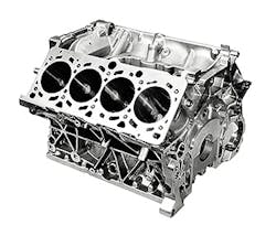
Precision is vital in manufacturing many high-value parts, particularly precision boring capability. The accuracy and finish of a multi-journal crank bore in an engine block relates directly to power and fuel efficiency, and the time it takes to achieve that precision is reflected in the engine manufacturer’s financial results. Precision bores in numerous engineered components are essential to critical performance metrics.
Such bores must meet critical tolerances, but that precision boring can be costly and time-consuming to achieve, with a small mistake or error turning potential valuable products into scrap. Kennametal recognizes this tension for manufacturers, and offers in response a geometric and asymmetric line boring bar product that it describes as “a revolution in the process.”
Boring (in contrast to drilling) is a machining process in which internal diameters are made in true relation to the spindle centerline. This is usually done with the workpiece held stationary and the cutting tool both rotating and advancing into the workpiece, although boring is also done with the cutting tool and the workpiece being adjustable.
Common applications for boring include the enlarging or finishing cored, pierced, or drilled holes and contoured internal surfaces. Related operations sometimes performed simultaneously with boring include turning, facing, chamfering, grooving, and threading.
Picture a small engine block with five in-line journals that require crank bores. Conventional thinking for a multi-journal finishing assignment, for example, involves a multi-blade guidepad reamer with the following suggested process (designated here as Option 1.0):
— A pilot reamer finishes the first journal
— The multi-blade reamer is fed in and semi- and final-finishes journals 2 through 5.
— The reamer is retracted.
The advantage of this a process is that it lends itself to use on CNC horizontal or multi-axis machining centers and does not require a dedicated boring machine with dedicated fixtures. However, depending on the size of the workpiece, the machine tool must be sufficiently rigid or the finished quality of the bore holes will be diminished.
Also, feed-in and feed-out of the reaming tool over finished bores must be done slowly and with precision or retraction marks and/or damage to the cutting edges will occur.
Another general option for machining this kind of bore is line boring (Option 2.0). The basic issue is determining how blades and the tool’s guide pads can pass through unfinished journals with smaller hole diameters?
CNC machine tool builders use conventional line boring bars and “counter-bearing” capabilities on their equipment. The process looks like this:
— The workpiece area of the machine tool lifts the cylinder block up
— The line boring bar is fed through the component into a bearing at the opposite end
— The cylinder block is adjusted down and clamped
— Crank bores are semi- and final-finished
— The cylinder block is lifted up and the boring bar retracted.
The process speeds up feed-in and feed-out, and because the tool is supported on both ends; the geometric quality of the finished bore is improved compared to reaming option 1.0.
On the downside, lift functions require special fixturing and CNC control, and the required counter-bearing on the fixture makes any additional back-side machining impossible.
Multi-axis machine tools with tilting worktables and/or tilting spindles together with more evolved boring bars contribute to line boring Option 2.1 with expandable guide pads, where the process evolves to the following:
— A pilot reamer is fed in and finishes journal 5
— The component (or machine table) gets rotated 180 degrees
— The machining center X-Y axis is adjusted to feed the boring bar in off-center
— The boring bar with guide pads is centered into journal 5
— Guide pads are expanded
— Journals 1 through 4 are semi- and final-finished
— Guide pads are fed back in
— The boring bar is retracted off-center
Option 2.1 uses the multi-axis adjustability of the machine tool. It retains the advantages of Option 1.0 by eliminating the need for any lift function or counterbearing, and of Option 2.0 with support on both ends of the tool. The disadvantages are that the complex internal mechanics of this type of boring bar are costly and can be difficult to handle. Insufficient lubrication can damage sensitive internal mechanics, and if not monitored for exactness, the tool can jam or hook in the workpiece and cause damage to the machine, fixture, tool, and part.
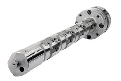
In collaboration with an automotive OEM’s engine block operations, Kennametal engineers advanced the range of boring options (Option 3.0) with “asymmetric line boring.” This is a geometric leap forward that accentuates the advantages of reaming and line boring while virtually eliminating the disadvantages of both.
As with most advanced solutions, the principle at the foundation is quite basic. Normal guide diameters are of full material or built of three or more guide pads, providing no degree of freedom from the bore wall while feeding in and out.
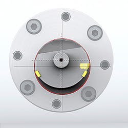
The Kennametal approach supports one guide pad in a setup similar to a typical guide pad reamer, but the guide pad, normally located 180 degrees to the cutting edge, was rotated so the resulting design provides freedom to enter and exit the guide part even passing through the raw bores. This geometry allows feeding the bar through raw bores on an eccentric path. The process looks like this:
— A pilot reamer is fed in and finishes journal 5
— The component (or machine table) gets rotated 180 degrees
— The asymmetric boring bar is fed in off-center using the machining center’s X-Y axis
— The tool is moved to the center and finishes journals 1 through 4 simultaneously
— The tool is retracted off-center with fast feed out.
Such asymmetric line boring retains all the advantages of established line boring techniques — high-quality precision bores, support on both ends of the tool — while no expensive lift functions, obstructive counter bearings, or critical mechanisms inside the tool are needed. It also adds the fact that complete feed-in and feed-out moves can be done at increased feed rates on conventional machining centers, adding efficiency to the process.
In addition, indexable inserts offered with this eccentric boring bar solution are advanced, too. High-precision RI8 inserts have eight cutting edges with pre-defined back taper, which allows high feed rates. Diameter can be adjusted to the precision of 1 micron. The high clamping force provided by the conical clamp screw avoids any settling effects.
Both inserts and the asymmetric boring bar are designed so the inserts clamp directly into the boring bar body. This eliminates the need for cartridges and the additional tolerances and space they require.
In short, asymmetric line-boring increases machining robustness, process speeds, and reduces tool maintenance and handling, all while being compatible with CNC machining centers.