Advancements in feature recognition are shaping tomorrow's CAM systems.
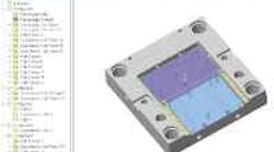
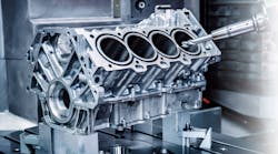
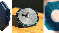
Toolpaths are now being created for features, such as the ones on this part, by feature recognition software. Every advance in this technology brings the manufacturing world closer to true point-and-click manufacturing.
Traditionally, creating toolpaths for CNC machines fell to CNC programmers. The job was tedious, and worse yet, didn't take advantage of all the information solid models offered, and it was this fact that led to early feature-recognition technology. These systems gave users a three-step process. First, a programmer picked certain entities and defined them as a feature. Secondly, he chose the proper machining process. And finally, the user supplied any necessary information the feature didn't provide.
While these early systems were a notable step forward, they left much to be desired. For instance, the three-step process had to be repeated for each feature to be machined. While the systems did define some geometry information automatically, they left the majority of the tedious work to the programmer. There was, however, one key benefit.
Once a feature and machining strategy were complete, changes in the feature automatically created the new toolpath. This freed up programmers for other work and helped those shops that had a shortage of programmers. Bottlenecks in manufacturing were still common, though, because if a model changed significantly — new features for instance — the three-step process started over.
With the advent of automatic feature recognition (AFR), feature programs searched a part for machinable features such as pockets, open-edge pockets, islands, and slots. Once recognized and defined, this information was available for numerous applications, including automatic inspection, manufacturing, cost estimating, feature-based editing of solid models, and CAM.
For CAM, AFR systems create operation plans, select a possible tool, and generate a tool-path with associated feeds and speeds from a user-defined database. This is possible through knowledge-based machining (KBM), which associates information via a technology database. With KBM, default machining information and parameters are easily applied to intelligent features. In addition, these tech databases are customizable, giving users another tool for automating the machining process.
True AFR involves a set of automated steps that apply no matter how many features the model contains. These steps are: extraction of machinable features; generation of an operation plan; and generation of a toolpath. As the number of features increases, there are exponential timesavings.
Today, AFR provides timesavings for many mill and turning parts. Still, development continues in other areas, including part recognition with numerous self-interacting features. Such features are difficult to interpret and present a challenge to the system. To address this, users can define feature templates for company-specific feature types.
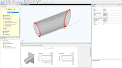
While most of AFR's progress focuses on recognizing the geometric properties of features, development is also taking place to add nongeo-metric information to AFR, such as threading data, tolerances, and finishes. For instance AFR technology from TekSoft analyzes the solid-model geometry and creates prismatic mill features such as holes, slots, pockets, and bosses as well as turning features. Mill pockets, slots, and bosses can then be defined with or without taper. Other AFR technologies analyze the design features that are used to model the part. This may seem a more logical approach at first glance, but it has limitations.
For example, it becomes difficult, if not impossible, to map design features to machining features. And if the solid model is not designed with a feature approach or is imported from a different design system, certain features may not be present.
TekSoft believes AFR has reached the stage where it increases the efficiency of taking a model from concept to finished part but has yet to reach the point where it takes a model from concept to finished part by itself. AFR is an algorithm, and complete automation 100% of the time is not a reality. Not all features are recognized, and some require revised machining parameters. This basic necessitates a method by which the user can inter-actively define a feature. Known as interactive feature recognition, it is another step in advancement of AFR technology.
To recognize irregular contours and apply the necessary machining strategies, initial AFR development was focused on user-definable feature recognition (UDFR). Here, the user selects a set of features, defines the recognition parameters (size, taper, angle), and the system automatically identifies these and applies the appropriate machining strategies as defined by a technology database. This, of course, can be applied to prismatic features.
With further advances, UDFR's recognition of 3D features will let users selectively apply multi-strategy machining techniques automatically, even if the features vary. For instance, users can define and extract a feature with 5° tapered walls and apply machining strategy "A," while the same feature with 10° tapered walls would get machining strategy "B."
In addition to programming itself, AFR can change the way estimates are prepared. Incorporating AFR, integrated estimating software pulls CAD information or CAD elements automatically. Estmating systems have scanned or digitized drawings for some time, but the use of AFR is new. The difference is that AFR estimating actually processes the part based on what it finds in the CAD file. All appropriate data is automatically filtered into the process plan for the estimating software. In as few as 30 sec, the estimator has a complete process plan for a part.
AFR benefits FEA by indicating a design change that might be realized automatically in the updated model and toolpath. On critical price-point parts, designers get a feel for the machining times and cost with the click of a few icons. These "computerized what-ifs" are key to overall profitability. Tools such as AFR, UDFR, and an integrated suite of products will become an integral part of decisionmaking.
A feature presentationBasically a feature is described as a "region of interest." Depending on the application, the definition of a feature can be very similar or significantly different. For example, a hole feature used to design and model a part will translate directly to a hole feature used for machining. However, multiple design features, such as cut extrudes, boss extrudes, fillets, and chamfers may translate into a single machining feature such as a pocket. Also key is the the difference between entities and machinable features. For many years CAM systems have been machining CAD entities such as lines, arcs, and surfaces. While CAD entities provide most of the geometric information required to create toolpath, other data needs to be supplied by the user, such as machining depth and machining parameters that are influenced by size and shape. Armed with this information, downstream toolpath generation can be further automated, and user input errors are minimized. |
