What shops should ask before selecting manufacturing software — from the basics to the hard questions.
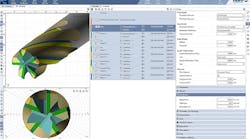
Five-axis machining at Delcam customer Rojac Tooling Technologies is easy to program thanks to PowerMill's modern interface.
The correct software, teamed with training and support, improves machining productivity. Photo courtesy of Mastercam.
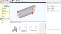
Software can address specific applications in a productive way. For example, IronCAD's add-on Fixture Builder targets CMM fixturing.
Solutions like think3's software go beyond 3D CAD to incorporate fully integrated 2D, 3D, and product-data management. As shown here, the software manages drawings, specifications, tracking changes, and revisions — it even generates hierarchical BOMs.
Ease-of-use is critical for CAM software such as GibbsCAM 2004, which employs a Windows-based approach.
According to Pathtrace, programs that combine solid models, automatic feature recognition, and a comprehensive tool database can improve a shop's automation capabilities.
Pathtrace's Job Manager lets shops share data with their customers, including news about specific jobs from the receipt of CAD data though individual machining processes.
Solid-modeling capabilities offered by companies like FeatureCAM let shops create physical mockups without the expense of physically building a part.
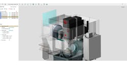
Esprit lets shops visualize the entire machining environment — including fixtures, clamps, stock materials, and workpieces — generated in dynamic solids.
Epicor's job costing/data collection system provides business analytics, reporting, and monitoring capabilities so shops can plan in a JIT environment.
Every shop buying manufacturing software probably starts by asking the same two questions: "Will the software do what we need it to do?" and "Will we be able to use it?" But where do they go from there? That answer depends on the package and the shop itself.
To select the right software and then correctly implement it, shops should begin by asking about basic training and support. Generally, it's a good idea to seek a provider that offers cus-
Every shop buying manufacturing software probably starts by asking the same two questions: "Will the software do what we need it to do?" and "Will we be able to use it?" But where do they go from there? That answer depends on the package and the shop itself.
To select the right software and then correctly implement it, shops should begin by asking about basic training and support. Generally, it's a good idea to seek a provider that offers customizable training, accessible 24/7 from even remote locations. This gives shop personnel the flexibility to learn the new system and expand their knowledge at their own pace and needs.
The second area to address is ease-of-use because shops shouldn't fight with their software to get things done. It's important to find out if tasks are straightforward or if personnel have to navigate a never-ending cascade of menu picks to get where they want to go. A program's functions should let both beginners and savvy experts use and make the most of the package. But beware systems that sacrifice flexibility and a full set of programming tools for the sake of user friendliness.
Software developers recom-mend that shops talk to one another to learn what they like/dislike about a particular program. It's also wise to check into the background of a developer or software vendor. Find out if it's financially stable and whether it has been successfully selling and supporting the software for years.
CAD/CAM concerns
When it comes to CAD/CAM, industry experts suggest the first question to ask is "Can this program make my parts?" While this may seem obvious, shops often overlook this basic concept when faced with a flashy demo or a bargain price.
Next, be concerned with flexibility. Shops making a few, complex parts have different needs than one running high-volume production; therefore, companies should be able to define their own sets of features along with specialized machining processes.
CAM systems typically provide a selection of standard features, but many companies specialize in a specific product that has its own set of standard shapes. In such cases, reports FeatureCAM/ Engineering Geometry Systems, Salt Lake City, it's easier for the company to create its own userdefined features and add them to the set of standard shapes already provided by the CAM system.
User-defined features define almost any 3D shape. Unlike static shapes saved in libraries, user-defined features let users enter the dimensions they want to use to create a special shape. The person defining the custom features then decides which dimensions are locked and which can be input by another party.
This customization also applies to user-defined operations. A shop should be able to define a customized process that controls specialized types of cutting passes and the order of those passes, including any specialized tools needed to perform the operation.
Because shops don't work in a vacuum, software should also integrate with other applications for visualization, collaboration, simulation, verification, and product-design management. Such collaboration tools, reports PTC, Needham, Mass., let CAD and CAM stakeholders resolve manufacturing, tooling, and design issues immediately — in real-time design conferences, for example — with the ability to save and manage information in an easily accessible, but secure, project repository.
Further integration is possible using software with robust data-exchange capabilities. This lets shops make major changes to a part design, even late in the development cycle. And if all the applications are built on a single architecture, the end user also gains fully associative CAD/CAM software from industrial design through NC. This means that downstream data translation is eliminated from the process, so that everyone works with the most-current model. And it eliminates countless hours of frustrating data repair, inefficient iterations, and late-stage changes that could cause major rework.
Conversely, shops should beware of CAD and data-management solutions made of separate, standalone systems that don't talk to each other, says Daniel Meyer, vice president of worldwide marketing, for think3 Inc., Cincinnati. "Making them work well together adds additional obstacles between your goals and what you can really accomplish," he comments. Therefore, Meyer suggests shops select a provider offering an integrated, modular technology scaled according to a company's needs. This solution can then be implemented step-by-step when the benefits are proven.
CAD counseling
When reviewing CAD software, shops should look closely at how easy it is to create a model from a print. For example, if an engineer normally works from drawings, he should have the software developer or vendor create geometry from a print during the demo. If time is short, ask that the demo model a section of a complex print — and request to see both 2D and 3D geometry creations.
Shops also want the ability to create, import, and export complex entities such as solids, Nurbs curves, and surfaces. This lets them model geometry easily, both in 2D and 3D. And shops importing geometries from customer CAD systems should use software that includes file translators for IGES, Parasolid, SAT (ACIS Solids), DWG, DXF, CADL, VDA, STL, and ASCII, recommends CNC Software Inc., Tolland, Conn.
Beyond creation and editing functions are other areas of concern, such as dealing with legacy data. This is critical because many shops reuse a vast amount of drawings and non-geometric data. So why give up archives, experience, and legacy in choosing new software?
According to think3's Meyer, legacy data often mandates a solution including 2D and 3D within the same product with full transparency — "so that shops don't spend time in flaky translations and alignment of data or shifting between products that don't talk to each other." He also suggests shops ensure that their existing drawings will load flawlessly in the 2D/ 3D system — blocks and symbols included.
Reusing legacy data also means existing 2D data shouldn't be recreated in 3D to be part of the bill of material (BOM) or the product structure. Shops using a CAD program with built-in design management can manage drawings and specifications, track changes, verify the latest revision, or determine every place a specific component is used, even generating and managing BOMs.
End users should also shop for CAD programs incorporating data-management functions. According to UGS PLM Solutions, Plano, Tex., these let shops share data with customers in a secure manner and en-sure that everyone is working on the most current version of a design. Key functions include secure vaulting of distributed product data — CAD models and drawings, related documents, and information about them — so that a design team can quickly and easily find, manage, and re-use engineering information. Such programs also provide automated revision-and-engineering-change management while managing the relationships between files and the product structure.
Process-specific applications may be of interest to some companies as well. For instance, says UGS PLM, CAD with specialized environments for sheetmetal, weldments, and tubing embody engineering-process knowledge in tailored commands and structured workflows that help design machinery more quickly than general-purpose CAD-modeling tools. This sheetmetal environment uses standard fabrication terminology, with streamlined modeling commands for tabs, flanges, louvers, dimples, cutouts, mitered corners, corner breaks, and other specific part features.
The CAM side
When it comes to CAM, shops should first determine what style of system is needed. According to Gibbs and Associates, Moorpark, Calif., CAM systems are either geometry-centric or process-centric. Geometry-centric systems are well suited to machining complex geometries, such as those found in mold, tool, and die applications. Process-centric systems, on the other hand, tackle process-intensive situations, such as those found in production machining.
Shops should align the type of machining they're doing with the type of CAM system they buy. Trying to get a CAM system to do something that is not part of its inherent orientation is a force fit, and a shop will end up spending significant time and energy to make the system do something that it's not set up to handle.
In general, software developers suggest shops evaluate CAM systems starting with toolpath generation. Says Brian Kindilien, vice president of sales at Surfware Inc., Westlake Village, Calif., "Quick and accurate toolpath generation is vital. No software or hardware wizardry can speed up NC programming if the CAM system's technique is inefficient. Checks need to be made along the way to allow design changes even while the tooling is being produced."
Optimized toolpaths produce the shortest number of program steps possible, and a short program cuts machine time. Hence, a CAM system should output data curve-fit within a specified tolerance to a series of arcs. This reduces the file size substantially, improves the surface finish, and allows higher feedrates.
It's also important that toolpaths are easy to edit for manufacturing changes. During a demonstration, shops should ask to see the full range of toolpath-editing capabilities. Watch out for the possibility that a superior toolpath editor exists to correct results from an inferior toolpath generator.
CAM systems usually generate toolpaths using a simple "up-andover" algorithm, but Kindilien cautions that this approach can cause unnecessary rapid and plunge moves, adding to machining time and creating gouges if the software doesn't check first. To avoid gouging, some CAM systems follow the part shape in the transition to the start of the next row.
Gouge and undercut avoidance is critical in a CAM system. To check the complete toolpath, the CAM system must take into account the type of tool, its full diameter and corner radius, shank diameter, flute height, and fixtures and clamps. But even systems that claim to generate gouge-free toolpaths may gouge on complex shapes. That's why shops should test CAM systems on the most complex part they're likely to cut. Even with gouge avoidance built in, it's beneficial to run the integrated verification module to display the material-removal process. This precaution detects cutting and rapid errors and compares the cavity or EDM electrode to the design model.
CAM systems offer a variety of cutting methods for solids or surface models, including Z-level roughing, Z-level finishing, planar, single-surface flow, multisurface-flow cutting (includes radial cutting), and project cutting. Machinists should have the option to specify various cutting methods for any portion of the model, says Surfware, adding that it's typical to require a 0.0002-in. accuracy or less for finishing cuts. For roughing passes, coarser toolpath information makes for shorter CNC programs. Surface machining usually requires a semifinish step between the rough and finish cuts.
In addition to toolpath generation, shops should check if a CAM system can load native solid models without translation, says Steve Sivitter, CEO of Pathtrace Engineering Systems Inc., Southfield, Mich. This ability reduces errors and greatly increases productivity because solid CAD models are created using features that are recognized by some CAM systems and used in the selection of tooling and machining operations. Sivitter adds that CAM systems combining solid models, automatic feature recognition, and a comprehensive tool database containing material, feed, and speed information, give shops an opportunity for more automation.
Knowledge-based machining
Certain CAM systems offer knowledge-based machining (KBM) that builds machining intelligence into the program. These systems increase efficiency by requiring less time to program parts and producing more-consistent NC code.
According to FeatureCAM/EGS, KBM can be incorporated into CAD/CAM systems at various levels:
Operations-based systems offer little to no KBM and require that users go through multiple steps to machine each part. These steps must be repeated one at a time for every operation on a part, making it a time-consuming process that is prone to error.
Process-based CAM systems reduce these steps by grouping operations in standard processes. The program remembers the processes used and repeats them for future operations. However, this method only works when a shop uses the same processes over and over for the same types of parts.
Feature-based CAM systems use a set of interrelated machinable features to describe a complete part and one or more associative operations that describe the preferred method for cutting that shape. A predefined set of machining rules and user preferences are then applied to the part.
According to FeatureCAM/EGS, this method builds the highest level of machining intelligence into the CAM system. Machinable features contain information and rules describing material removal, cutting depths, preferred machining strategies for roughing and finishing, and so forth. The CAM system evaluates part geometry and material, then automatically selects the most appropriate tools and operations, recommends machining strategies, calculates feeds and speeds, and automatically generates the NC code.
Matching machine tool advancements
Many software developers recommend that end users select a CAD/ CAM system that allows them to move into more-advanced manufacturing techniques — in particular, multitasking and high-speed machining.
In multitasking, a B-axis turn/mill machine provides the additional capabilities of a 5-axis machining center by allowing additional tool rotation for machining on compound angles. These machines support the entire range of milling and turning operations, and they do it in one workholding setup.
CAD software should support the creation of these types of parts, and CAM software needs to handle machining on regular turn/mill and B-axis turn/mill machines. This includes support for multiple spindles and multiple turrets, where several operations may be performed simultaneously.
As for high-speed machining, CAM developers use a variety of strategies. First, the order of operations can facilitate part stiffness. Stock needs to be left to support thin features that are likely to deflect under the forces of machining. Toolpaths should be created to avoid sharp changes in direction and favor wide radius moves. Tool-paths must also minimize moves that could bury the tool in material.
Offline verification of high-speed toolpaths is also critical, as well as automation techniques. Taking too long to program a part can wipe out time and cost savings gained from high-speed machining.
Output NC code
Many CAD/CAM systems use translation programs called postprocessors to customize the NC code output. Sometimes these post-processors are part of the program, and sometimes they are add-ons. Therefore, users should ask if the software price includes post-processors.
CNC Software suggests some other important questions to ask about NC-code output:
- What is the cost to provide posts for all your machines? (And what is the cost to get additional posts later?)
- How much are posts for multiple-axis controls?
- Who will customize the NC output for your controls and shop practices? Will the reseller customize the post-processors, or will the software company make the changes?
- Are post-processors customizable by the user?
- Is it easy to switch a program between machines? In some CAD/CAM systems, the same tool-paths simply go through a different post-processor. Others require that users reprogram parts from scratch.
- Is visualization of NC-code output available for toolpath verification?
CNC simulation and optimization
Besides using CAD/CAM, shops employ CNC simulation and optimization software to improve quality, efficiency, and profitability. For example, simulation lets shops detect mistakes early in the manufacturing process, before committing extensive resources. According to experts at Applied Computing & Engineering Ltd., Warrington, England, and Adept Technology Inc., Livermore, Calif., which are jointly developing such software, shops that reproduce an entire machining environment often detect problems that would otherwise lead to collisions and interferences with fixtures and other machine tool components.
The best software should have the power and ability to accurately model the real machining environment, says CGTech, Irvine, Calif. For instance, does it simulate a control's specific G-codes or is it limited to a CAM system's data format? Shops want software that verifies programs generated by different CAM systems. They should also find out if the software can perform multi-axis operations, support multiple setups, simulate complex tool shapes, and model fixtures and toolholders.
In addition, does the simulation go beyond the simple visual check of the NC toolpath? The software needs in-depth measurement and model-analysis capabilities. Can it measure all the machined features of a part and provide details such as cut-feature information, stock thickness, volumes, depths, gaps, distances between features, and so forth? And are these measurements accurate and reliable?
CGTech also recommends shops look for simulation software that simultaneously models material removal and machine motion in the same integrated package. This ensures collisions are detected between machine components and the as-cut workpiece.
Another important question to answer is if the software can handle large and complex NC programs. Shops don't want a program that starts out quickly, only to slow down to an unusable crawl midway through the simulation.
And finally, shops typically model a number of machining operations. While some simulation packages use separate software to replicate different operations, CGTech advises shops acquire an integrated package that simulates all its machining requirements. The resulting as-cut model should move seamlessly between operations, regardless of the operation or machine used.
Managing an operation
What should end users look for in shop-management software? They should begin by defining what's important to them, comments Rich Hanson, JobBoss senior regional sales manager for Exact Software, Minneapolis. Some shops may need a system that handles all the variables of costing. For instance, a tooling shop may require a system that accommodates progress payments, allows them to ship, and continues to accumulate labor and material costs. A screw-machine shop, on the other hand, may have accumulated all its costs at the time of shipping. So the same costing system may not meet the needs of each of these companies.
Shops should also search for systems that fully integrate manufacturing, costing, and accounting, remarks Billie Henning, vice president of Henning Industrial Software, Hudson, Ohio. That's because errors can crop up when transferring between different programs and databases. Data should only be defined once, she says, and end users should be able to tie back to the original transaction when auditing.
Other key capabilities to look for are job costing/data collection and scheduling/production planning, which, according to Epicor Software Corp., Minneapolis, are cornerstones of manufacturing systems.
KSI Technologies, Rockledge, Fla., suggests end users ask the following questions when considering enterprise-resource-management software:
- How comprehensive is it? (Does it cover everything from estimating through accounting?) And are the modules integrated to eliminate the need for duplicate data entry?
- How flexible is the product? (Will it allow a shop to do whatever it needs to do to get an order out?)
- Does the scheduling module offer forward finite, forward-infinite, and backward-infinite scheduling? An infinite schedule determines where bottlenecks are, but only a finite schedule actually indicates if a job will be finished on time.
- How long does it take to find the following information:
- When was the order scheduled for shipment?
- Exactly where is the job in production?
- Has the material been ordered and/or issued to the job?
- How many parts have been processed through the individual operations?
- Is the product scaleable (capable of handling additional users) for future needs?
Manufacturing software
| Company | CAD | CAM | Solids Modeling | Surface Modeling | Simulation (machine and process) | Reverse Eng. (Digitizing) | Drawing/ Design | CNC Capabilities | NC/CNC Verification | Product Lifecycle Management | Cost Estimating | Data Conversion | Product Data Management | Enterprise Resource Planning |
| Adept Technology Inc. adept.com Applied Computing & Eng. Ltd. acel.co.uk | Cimstation Robotics, Adept Visual Workcell | SoftMachines | Production Pilot Suite | |||||||||||
| CGTech | Vericut | Vericut | Vericut | Vericut | ||||||||||
| Cimatron Technologies Inc. Novi, Mich. cimatron.com | ||||||||||||||
| Delcam Inc. Windsor, Ont. delcam.com | PowerShape | PowerMill | PowerShape | PowerShape | CopyCAD | PS-Draft | PowerMill | PowerMill | PS-Exchange | PS-Team | ||||
| DP Technology Corp. Camarillo, Calif. dptechnology.com | Esprit 2003 | Esprit 2003 | Esprit 2003 | Esprit 2003 | Esprit 2003 | Esprit 2003 | Esprit 2003 | Esprit 2003 | Esprit 2003 | Esprit 2003 | ||||
| Epicor Software Corp. Irvine, Calif. epicor.com | Vista | Vista | Vista | Vista | ||||||||||
| Engineering Geometry Systems Salt Lake City featurecam.com | FeatureMill2.5D, FeatureMill3D, FeatureTurn, FeatureTurn/Mill, FeatureWire | FeatureMill2.5D, FeatureMill3D, FeatureTurn, FeatureTurn/Mill, FeatureWire | Solid Modeling Option for Feature Mill2.5D, FeatureMill3D, FeatureTurn, FeatureTurn/Mill | FeatureMill3D | FeatureMill2.5D, FeatureMill3D, FeatureTurn, FeatureTurn/Mill, FeatureWire | FeatureMill2.5D, FeatureMill3D | FeatureMill2.5D FeatureMill3D, FeatureTurn, FeatureTurn/Mill, FeatureWire | FeatureMill2.5D, FeatureMill3D, FeatureTurn, FeatureTurn/Mill, FeatureWire | FeatureMill2.5D, FeatureMill3D, FeatureTurn, FeatureTurn/Mill, FeatureWire | FeatureMill2.5D, FeatureMill3D, FeatureTurn, FeatureTurn/Mill, FeatureWire | FeatureMill2.5D, FeatureMill3D, FeatureTurn, FeatureTurn/Mill, FeatureWire | |||
| Gibbs and Associates Moorpark, Calif. GibbsCAM.com | GibbsCAM | GibbsCAM | GibbsCAM | GibbsCAM | GibbsCAM | GibbsCAM | ||||||||
| Henning Industrial Software Inc. Hudson, Ohio henningsoftware.com | Visual EstiTrack | Visual EstiTrack | Visual EstiTrack | Visual EstiTrack | ||||||||||
| IronCAD LLC Atlanta ironcad.com | IronCAD Inovate | IronCAD Inovate | IronCAD Inovate | |||||||||||
| KSI Technologies Rockledge, Fla. ksitech.com | Shop Mate | Shop Mate | Shop Mate | |||||||||||
| MasterCAM/ CNC Software Tolland, Conn. mastercam.com | Mastercam Design Mastercam Mill Mastercam Lathe Mastercam Wire Mastercam Router | Mastercam Mill Mastercam Lathe Mastercam Lathe Mastercam Wire Mastercam Router | Mastercam Solids | Mastercam Design Mastercam Mill Mastercam Lathe Mastercam Wire Mastercam Router | Mastercam Draft Design, Mill, Lathe, Wire, and Router | Mastercam Mill Mastercam Lathe Mastercam Wire Mastercam Router | Mastercam Mill Mastercam Lathe Mastercam Wire Mastercam Router | |||||||
| Surfware Inc. Westlake Village, Calif. surfware.com | SurfCAM | SurfCAM | SurfCAM | SurfCAM | SurfCAM | SurfCAM | SurfCAM | SurfCAM | SurfCAM | SurfCAM | ||||
| think3 Inc. Cincinnati think3.com | thinkdesign, thinkiD | thinkdesign | thinkiD | Raindrop Geomagic, Pointmaster | thinkdesign | Thinkteam, Product Configurator |
Monitoring Systems
Productivity-monitoring packages like CNC Engineering's Manufacturing Event Monitoring provides real-time feedback on productivity and produces daily, weekly, and monthly management reports.
Shops monitor their processes and machines in a variety of ways. For instance, productivity-monitoring packages keep track of manufacturing events, gain real-time feedback, and gather information for daily, weekly, and monthly management reports. Shops may also employ machine-monitoring packages to keep tabs on their machines and collect real-time production data.
On the productivity-monitoring side, CNC Engineering Inc., Enfield, Conn., advocates solutions that address immediate concerns. According to James D. Smith, vice president of software operations, shops should use "triage" for implementing such software. "Consider, for a moment, faltering company 'F' bringing in multiple software vendors, forming research committees, building benefit-analysis grids, and pitting vendor against vendor with impossible multilevel integration demands and 'apples versus oranges' price bidding," he describes. "At the same time, thriving company 'T' is busy implementing creative solutions from reliable suppliers, reducing costs, and happily taking market share."
Smith says there is a need for thorough analysis and inter-department consensus when making corporate-wide software purchases, but using that "corporate committee" model for purchasing task-specific software may not always be the best strategy in today's competitive international marketplace.
"The natural temptation is to find a comprehensive, fully integrated solution that will solve multiple problems simultaneously," remarks Smith. Instead, he recommends that shops identify their most urgent problems and focus on them one at a time. They can always implement a "comprehensive" solution later.
As for machine-monitoring systems, shops use them to keep track of information such as spindle-on time, true cycle time, machine uptime, and setup time. These packages can also supply accurate part counts, preventive-maintenance logs, and tool-breakage data.
Keeping track of these factors provides a number of production benefits, claims Port CNC Inc., Greenfield, Wis. For example, shops can gain the ability to monitor controller-generated data. This shows if a machine is running, in setup mode, or idle. This portion of the monitoring system allows companies to configure the system to track data most relevant to their operation.
Shops can also focus on reasons for machine downtime, such as waiting for support personnel. Machine monitoring also lets companies quantify the amount of time being lost, investigate the reason for the losses, and put solutions in place to eliminate these problems.
Finally, machine monitoring creates accountability in labor reporting, says Port CNC. Such systems keep track of the exact number of machining cycles that have run, indicate when a spindle is running, and count how many times a program cycle starts. All of this gives management valuable information about machine use.
AM Manufacturing Software SolutionsLike many other small shops, American Machinist Mfg. Co. requires flexibility and quick turnaround to design and produce short runs of complex components. Hence, the company needs to upgrade from 2D to 3D CAD. In addition, it wants an integrated CAD/CAM package that includes built-in translators. This type of software will accommodate the company's legacy data and allow it to accept customer files in a variety of formats. It should also boost machine use by reducing the time used to calculate toolpaths. Because its part designs typically require several iterations, the company wants software with feature-based CAM capabilities. This will let it change part features and automatically update associated operations. In addition, AM Mfg. is shopping for a CAD/CAM package that supports machining on various machine types. Because machine tools involve a considerable investment — and a certain level of programming capability — AM Mfg. has also opted for CNC simulation and optimization software to verify machining programs. Finally, the company is adding PDM software to integrate manufacturing, costing, and accounting. |
AcknowledgmentsIn addition to the companies listed in the "Manufacturing software" chart, which appears in this article, AMERICAN MACHINIST would like to thank the following companies for their contributions: CNC Engineering Inc., Enfield, Conn. |
