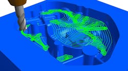
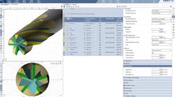
Delcam will demonstrate its new Vortex strategy for high-speed area clearance at IMTS. Vortex will be the major enhancement for the 2013 release of Delcam’s PowerMILL CAM system for high-speed and five-axis machining that will be launched during the event. The new strategy also will be added to Delcam’s FeatureCAM software for feature-based programming, and the PartMaker system for programming Swiss-type lathes and mil-turn equipment later this year.
Vortex, for which Delcam has a patent pending, was developed specifically to gain the maximum benefit from solid-carbide tooling, in particular those designs that can give deeper cuts by using the full flute length as the cutting surface. It can be used for two- and three-axis roughing, three-plus-two-axis area clearance and for rest machining based on stock models or reference toolpaths.
Like other Delcam roughing strategies, Vortex toolpaths are calculated to give more efficient machining by following the shape of the part and by keeping air moves to a minimum. This is particularly important for rest machining operations.
One fundamental problem with conventional area-clearance strategies is that the optimal cutting conditions occur only during a straight-line cut. Any internal corners within the model increase significantly the engagement angle of the cutter. To protect the cutter, this increase needs to be balanced by setting a lower feed rate. Then, the user has the choice of using this lower rate over the whole toolpath, which increases the machining time, or varying the feeds and speeds as the cutter moves around the model and so increasing wear on the cutter.
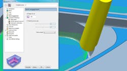
Unlike other high-speed roughing techniques that aim to maintain a constant theoretical metal-removal rate, the Vortex strategy produces toolpaths with a controlled engagement angle for the complete operation. This maintains optimal cutting conditions for the entire toolpath, which normally would be possible only for the straight-line moves. As a result, the cutting time will be shorter, while cutting will be undertaken at a more consistent volume-removal rate and feed rate, so protecting the machine.
Because Vortex toolpaths have a controlled engagement angle, tools will never be overloaded and so will achieve the maximum tool life. Shock loading caused by changes in the contact angle is minimized, preventing chipping of the flutes. In addition, the stability of the cutting conditions gives more consistent edge temperatures, so prolonging the life of the tool coating and removing heat damage to the surface of the part. Finally, the ability to use stepdowns of up to two, or even three times, the tool diameter spreads the tool wear evenly over the cutting surface of the tool, again contributing to longer tool life.
“Anyone using the Vortex strategy will be able to hear the difference immediately,” according to Mark Forth, product manager for Delcam’s Advanced Manufacturing Solutions. “Conventional roughing produces a sound of varying pitch, which indicates tool overload and chatter, while Vortex roughing gives a constant pitch, showing that the tool is operating under consistent conditions. Users will also be able to see the difference in the regular size and thickness of the chips produced, providing further evidence of the consistency of the cut.”
The new Vortex toolpaths benefit from the general advantages of PowerMILL, including support for 64-bit computing and multi-processor operation to minimize calculation times, plus the comprehensive options for leads and links. Furthermore, they can be used in association with the step-cutting strategy introduced in PowerMILL 2012 R2. This approach minimizes the terracing that can result from using a large stepdown by moving back up the part and automatically generating extra toolpaths to remove additional material at intermediate slices. It optimizes the amount of material that can be removed with a single tool as well as helps to maintain a more consistent removal rate by increasing the feed rate for the intermediate slices.
