By Scott Collins
Senior vice president
Product Development
Anark Corporation.
(www.anarkcom)
The preparation of 3D CAD files is critical in sharing files with others and involves the redaction of information, security measures and reduction of geometry size and complexity.
The key problem that surrounds the task of CAD data preparation is that it is typically a manual process. The lack of automation for CAD data preparation has been something that engineers have put up with, and worked around, for so long that it seems a normal part of the process. However, that is changing.
A recent industry survey conducted by CADCAMNet (www.cadcamnet.com) showed that almost 60 percent of original equipment manufacturers (OEMs) send up to 1,000 CAD files every month to suppliers, partners and contractors, and another 20 percent send 1,000 to 10,000 files every month.
Respondents to the survey said that each of their engineers spends an average of 3 hours to 4 hours each week preparing data for transmission, and another 3 hours on translation of files. Alarmingly, engineers at supplier companies who receive the data spend 6 hours to 10 hours each per week on the same problems.
The survey raises the question: What is involved in “CAD data preparation for transmission and sharing?”
CAD data translation and preparation can take many forms, depending upon the CAD systems in use, preferred formats, product data selected, need for protection of trade secrets and the use of the data once it is received. Typical-use cases include: OEM-supplier data exchange, CAE, visualization-simulation, product support, and technical publications.
CAD Translation
The first key problem to exchanging CAD data is interoperability. It is as old as the CAD industry itself, and is all about finding a way to exchange CAD data with others in a way they can read it, view it, and use it.
That is a problem because just about every 3D CAD system is based on its own proprietary format that doesn’t share common methods for describing product geometry and associated metadata.
The lack of a common geometry language makes translation between CAD packages difficult because a designer’s intent can be described in many different ways. For example, how do you describe an arbitrary curve that forms the edge boundary within an “organically” shaped solid?
So how do manufacturing OEMs tackle the CAD translation process?
They work in stages:
First, they attempt to exchange files with a chosen supplier using native formats.
If that doesn’t work, they try a different process using an exchange format such as STEP or IGES.
And if that proves inadequate, they start testing third-party interoperability software that provides varying levels of translation capabilities.
Feature-based CAD Translation
There are only a few companies that offer “feature-based translation” between CAD packages.
Feature-based translators provide varying levels of success but are unwarranted when product designs won’t be edited. In these use cases, “dumb” B-rep solids are often preferred for:
Computational fluid dynamics and finite element analysis.
An exchange of data between an original equipment manufacturer and a supplier.
In tests for form, fit and function.
CAD Interoperability: More Than CAD Translation
Many CAD vendors now provide some level of interoperability, including support for neutral file formats such as STEP and IGES formats.
There are also numerous CAD translation solutions available, but in discussions with customers we often find that the problem of “translation” between formats is only one aspect of the interoperability puzzle.
Translation alone doesn’t solve the issue of how to minimize the time spent preparing CAD files for specific use cases. It goes a step further into what we call “transformation.”
Transformation of CAD files
Transformation of CAD data takes a broader view of exchanging files that includes not just translation, but also tackles ways to provide case specific CAD geometry to all the parties that depend on it for their job function based on the level of detail that should be revealed to various suppliers, contractors and other parties.
As a new concept to describe the problem, “transformation” is the entire process of preparing CAD data for a particular use by removing unwanted product information, or equivalently, isolating the necessary product information, and providing such data in the correct format and the correct form and at the correct depth for a specific person to fulfill his duties.
Restructuring: Providing the Correct Product Structure
One company’s assembly is another company’s part.
Engineers who are responsible for preparing supply-chain CAD data can spend hours removing surrounding assemblies and extraneous parts, collapsing assemblies into multi-body parts and preparing the data for their own, or for their partners’, CAD systems.
This same situation arises in another form during mechanical simulation. Engineers that perform simulation often require the redefinition of kinematic relationships within the product structure. Flat assembly structures become deeper and naming conventions change.
De-featuring: Removing Irrelevant, Unwanted, or Confidential Detail
Engineers who perform CAE analysis on parts or assemblies can spend hours removing unwanted part detail that complicate the calculations or make them impossible.
In the case of supply-chain data exchange, the issue of trade secrets and intellectual property becomes pertinent.
There is a very real danger that if too much information is given to an unscrupulous supplier, an entire product design could be compromised. With that in mind, an OEM needs to work out exactly what data each supplier requires to do his job.
Automated Transformation is the Key
Interoperability is a multidimensional problem best described by the concept of “transformation” that includes translation to different file formats, restructuring, attenuation of unnecessary detail, and the production of case specific CAD models that have been derived from the “source” design.
The convenience of using and designing with 3D CAD data results in a series of unintended consequences that force engineers to manually transform 3D CAD datasets. Unfortunately, conventional 3D CAD design tools themselves can be cumbersome and expensive, and can have little or no automation of these processes.
As result, engineers have to make such transformations manually — and repetitively when designs change.
The reality is that while 3D assemblies are getting larger and more complex as a result of improved functionality of 3D CAD, this ‘back end’ part of the process has not been solved.
Engineers are basically doing it manually, and automation is needed.
Automation provides another benefit in that the transformation can be performed reliably, helping to minimize the chance that a sensitive change might not be recorded properly because of human error.
In the recent survey of OEMs, the respondents noted that they felt geometry translation errors were the most important element to fix in interoperability, but that automation of the processes comes a close second in importance.
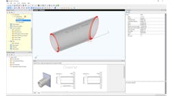
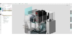
This is where the Anark Core Platform comes into play. The software delivers an easy-to-use CAD tool and optional server product that can perform translation, healing, redaction, restructuring, and defeaturing in an automated environment.
After a quick installation process on either a workstation or a server system, the software can be set up to perform user-created “recipes” that tackle groups of files in prescribed ways.
With these recipes, the software automates the transformation of 3D CAD data into new case specific representations while maintaining the precision and integrity of the original parts and assemblies.
Anark Core is not a design tool, and is designed to be very easy to learn and use. It is suitable for engineers, but it is a tool that is not limited to engineering use, so it can be managed by other technical software users who have limited expertise with CAD software systems.
